Welcome to FujiNet!
FujiNet1 is more than just a device, it’s a community! FujiNet brings vintage computer enthusiasts together through the power of the Internet by connecting computers to networks & providing a wealth of peripherals to interact with. While FujiNet is often best known for its ability to mount disks and other media over wireless networks, it also provides a collection of the most popular peripherals that vintage computer users would expect to work with their machines back in the day. From modems to printers, the FujiNet provides it all!
FujiNet Documentation
We welcome you to make the most of your FujiNet device(s) by providing extensive documentation covering both the functionality built-in to FujiNet as well as how enterprising developers can extend the device in innovative ways.
Join the Community
Get involved in the FujiNet community to learn even more or help us make FujiNet even better!
-
FujiNet’s official homepage is at https://fujinet.online ↩
What is FujiNet?
FujiNet is an hardware device for older computer systems that do not have native solutions for participating on the modern Internet in order to load and manipulate software images and data for native applications. Its simplest use-case– it can load disk images for the supported platform from remote resources via local WiFi– it replaces actual floppy drives. It can also replace physical printers and modems. It can offload complex modern Internet protocols from the target platform (like HTTPS and JSON parsing) to allow local apps to treat network resources like native physical devices. It can also be used without networking to load disk images from its microSD card slot.
Platform Overview
The following pages provide a very high-level overview of each of the various platforms supported by FujiNet. While FujiNet is a unified device striving to provide a consistent set of functionality, each platform has its own unique capabilities, strengths, & weaknesses. Review the pages in this section to understand what FujiNet features are currently supported for each platform.
Apple II/III
Provided Devices
| Device | Status | Notes |
|---|
More Information
Atari
In some cases, the devices FujiNet provides are meant to simulate real Atari peripherals, such as floppy disk drives (D: devices), RS232 and modem interfaces (R: devices), and more.
Utilizing the device’s Wi-Fi networking capabilities, it’s possible to connect to other devices on a local network or Internet, e.g. Bulletin Board Systems (BBSes) or other systems over Telnet, or even mounting floppy disk images from the “cloud”.
Provided Devices
| Device | Status | Notes |
|---|---|---|
| C: (Cassette) | Prototype Working | Load a CAS image (FUJI format) from MicroSD named test.cas. Write CAS file to MicroSD. Use browser to set PLAY or RECORD state. Short-press Button B to enable the C: device. Install a 10-kohm pulldown resistor on the MOTOR line. |
| D: (Disk) | Working | Load floppy disk images from onboard MicroSD or networked TNFS server. Currently supports ATR and XEX. ATX in progress |
| N: (Network) | Working / In Progress | NEW networking device. FujiNet configuration commands in place and working (WiFi, mounting, etc). TCP/UDP working. Handler in progress. |
| Other | SIO2BT Bluetooth Connection. Apetime Real Time Clock (NTP). SAM Text To Speech as a printer, voice output from #FujiNet to Atari. MIDIMaze network gaming. | |
| P: (Printer) | Working | Printer output saved to PDF files downloadable from the device. Available Printers: 820, 822, 825, 1020, 1025, 1027, 1029, Espon 80, Okimate 10, HTML for copy/paste, GRANTIC Screen Printer. |
| R: (Modem) | Working | 850 Modem emulation, supports Type 1 Poll to load handler. Works with existing communications programs such as Ice-T, BobTerm, AMODEM, PLATOTERM, and BBS servers. |
Since devices are handled via the Atari OS’s Central I/O (CIO) subsystem, practically any programming language on the Atari will be able to make use of these network features. For example, here’s a simple networked program in BASIC:
10 OPEN #1,12,0,"N:HTTP://WWW.GOOGLE.COM/"
20 DIM A$(1024):TRAP 100
30 INPUT #1,A$:PRINT A$:GOTO 30
100 CLOSE #1
On top of TLS and UDP, cryptographic protocols designed to provide communications security over computer networks, Transport Layer Security (TLS) and Datagram Transport Layer Security (DTLS) respectively, are also a possibility, thanks to the computing horsepower of device powering FujiNet.
More information
The information from the “#FujiNet - a WIP SIO Network Adapter for the Atari 8-bit” thread on the AtariAge forums should all be covered here in the wiki, and/or on the FujiNet website. For now, visit that thread for more info.
Atari Lynx
Provided Devices
| Device | Status | Notes |
|---|
More Information
Coleco ADAM
Provided Devices
| Device | Status | Notes |
|---|
More Information
Commodore C64/C128
Provided Devices
| Device | Status | Notes |
|---|
More Information
PC - MS-DOS RS232
Provided Devices
| Device | Status | Notes |
|---|
More Information
Tandy CoCo
Provided Devices
| Device | Status | Notes |
|---|
More Information
Using FujiNet
Quickstart Guides
Choose the quickstart guide for your platform to get up and running with FujiNet as quickly as possible.
Each guide covers the essentials: hardware overview, connecting the device, first boot, WiFi configuration, and basic usage.
Available Platforms
| Platform | Interface | Status |
|---|---|---|
| Atari 8-bit | SIO Bus | Stable / Complete |
| Apple II & III | SmartPort / Disk II | Stable / Complete |
| Coleco ADAM | AdamNet | Stable / Complete |
| Commodore 64 | IEC Bus | Beta / In Development |
| PC MS-DOS (RS232) | Serial RS-232 | Beta / In Development |
| Virtual FujiNet | Emulator (no hardware needed) | Stable |
Tip: If you don’t have any retro hardware, you can try FujiNet right now using the Virtual FujiNet guide with just your modern computer!
Common First Steps
Regardless of your platform, you’ll generally follow these steps:
flowchart LR
    A[Connect FujiNet\nto your computer] --> B[Power on\nand boot]
    B --> C[Configure\nWiFi]
    C --> D[Browse hosts\nand mount disks]
    D --> E[Boot your\nfavorite software!]
Important: FujiNet uses the ESP32 chipset, which operates on 2.4 GHz WiFi only. If you have a dual-band (2.4/5 GHz) router with a shared SSID, you may experience connectivity issues. Consider setting up a dedicated 2.4 GHz SSID if problems arise.
Need Help?
- Join the FujiNet Discord community for real-time support
- Visit fujinet.online for the latest news and downloads
- Check the User FAQ for common questions
Atari 8-bit Quickstart Guide
Welcome to the FujiNet quickstart guide for the Atari 8-bit computer family. This guide covers initial setup, WiFi configuration, and basic disk image mounting. For a broader overview of what FujiNet can do across all platforms, see the Platform Overview.
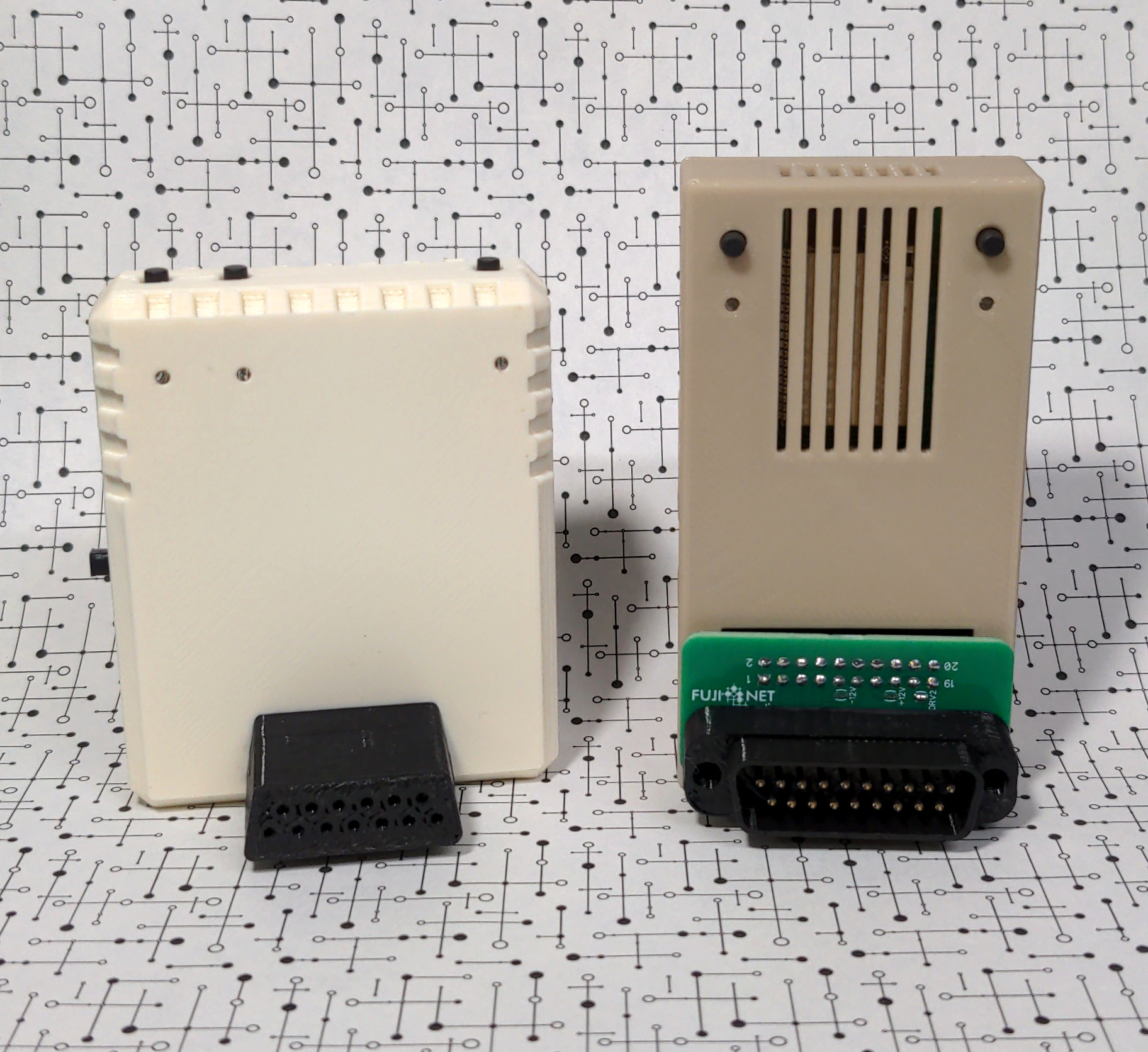
Getting to Know Your FujiNet
With the SIO plug (which connects to your Atari) facing you, the FujiNet hardware is laid out as follows:
Physical Layout
| Location | Feature | Details |
|---|---|---|
| Top left | Buttons A and B | Disk swap, debug, safe reset (see Buttons below) |
| Top right | Reset button | Returns to CONFIG on next reboot |
| Left side | Micro USB or USB-C port | Power and serial debugging |
| Left side | Power switch | Down = Off, Up = On |
| Right side | Micro-SD card slot | Local storage for disk images and configuration |
| Front | SIO plug | Connects to your Atari |
| Back | SIO receptacle | Daisy-chain other SIO devices |
Micro-SD Card
The Micro-SD card slot uses a tension-mounted (not spring-loaded) mechanism. Insert the card with the metal contacts facing toward the Atari (toward the SIO plug).
Important: The Micro-SD card must be formatted as FAT32. Cards of 32 GB or smaller are recommended, as larger cards have been reported to cause issues. A 2 GB card is more than sufficient for most use cases.
LED Indicators
| LED (left to right) | Color | Meaning |
|---|---|---|
| Left | White | WiFi enabled |
| Middle | Blue | Bluetooth enabled |
| Right | Orange | SIO activity |
Buttons
| Button | Action | Function |
|---|---|---|
| A | Tap | Disk swap |
| A | Hold | Toggle SIO2BT mode (requires SIO2BT firmware) |
| B | Tap | Print debug info to serial console |
| B | Hold | Safe reset (unmounts SD card before reboot) |
| B | Hold on power-up | Reset FujiNet configuration |
| Reset | Press | On next Atari reboot, return to CONFIG instead of booting the disk in slot 1 |
Connecting Your FujiNet
Follow these steps to connect FujiNet to your Atari for the first time:
flowchart TD
    A[Power off Atari and FujiNet] --> B[Remove any cartridges]
    B --> C[Disconnect any existing SIO devices]
    C --> D[Plug FujiNet into Atari SIO port]
    D --> E[Ensure FujiNet power switch is ON]
    E --> F[Optionally connect USB power]
    F --> G[Turn on Atari]
- Start with your Atari computer and FujiNet both powered off.
- Remove any cartridges from your Atari’s cartridge slot.
- Remove any SIO cable or device currently connected to your Atari’s SIO peripheral port.
- Plug the FujiNet firmly into your Atari’s SIO peripheral port.
- For now, do not plug anything into the FujiNet’s SIO receptacle (back port).
- Optionally, provide power to the FujiNet via a USB cable.
- Make sure the FujiNet’s power switch is in the “On” position (up).
Note – Atari 400/800 Users: The Atari 400/800 (or XL/XE systems running the 800 OS) currently require external USB power for FujiNet, because FujiNet does not come online fast enough from SIO bus power alone. A workaround: power on the 800 while holding Start (to attempt a cassette boot), wait for FujiNet to fully power up, then press Reset to reboot into CONFIG.
Note – Persistent Mounts: If you connect external USB power to your FujiNet, it will keep settings active (such as mounted disks) even when the Atari is powered off. This is useful if you need to keep disks mounted between boots.
Boot Up and Connect to WiFi
- Turn on your Atari computer.
- FujiNet will begin responding as disk drive #1. The rightmost (orange) LED will blink, and you should hear SIO activity beeping from your TV or monitor speaker.
- The FujiNet CONFIG program will appear on screen.
- Choose your WiFi network from the list, or select
<Enter a specific SSID>to type it manually. Press Esc to rescan for networks. - Enter your WiFi network password, if required.
- If the password is correct, you will see the “Connected to Network” confirmation screen.
- Once connected, the Host and Slot screen will appear, and you are ready to mount disk images.
Important: FujiNet uses the Espressif ESP32 chipset, which operates on 2.4 GHz WiFi only. If you use a dual-band (2.4/5 GHz) router with a shared SSID, you may experience connectivity issues. Symptoms include inability to ping the FujiNet, connect to TNFS servers, or reach the web interface. Consider setting up a dedicated 2.4 GHz SSID if problems arise.
How Booting Works
When you turn on (or reboot) your Atari, it searches for devices on the SIO bus. Any device responding as “disk drive #1” (D1:) will be used for booting – whether that is a real floppy drive, a virtual drive (SIO2SD, SDriveMax), or FujiNet.
When FujiNet is connected and powered on, if no other device responds as D1: after a moment, FujiNet will respond. It will either boot the disk image mounted in its drive slot 1, or load the CONFIG program.
| Scenario | Result |
|---|---|
| No disk in slot 1, no other D1 device | FujiNet boots into CONFIG |
| Disk image in slot 1, no other D1 device | FujiNet boots the mounted disk image |
| Another device responds as D1 | That device boots; FujiNet provides other drive slots |
| Hold Select during boot | FujiNet skips auto-WiFi, allowing you to reconfigure the network |
Navigating CONFIG
After initial WiFi setup, booting into CONFIG displays the main screen with two sections:
- TNFS Host List (top) – sources for disk images
- Drive Slots (bottom) – virtual floppy drives seen by the Atari as
D1:throughD8:
Each section has 8 entries. Use the arrow keys, joystick up/down, or the 1 through 8 keys to move between entries. Press Tab to switch between the host list and drive slots.
TNFS Host List
Press E to edit a host slot. Enter one of the following:
| Entry | Description |
|---|---|
SD | Access files on the inserted Micro-SD card |
Hostname (e.g., fujinet.online) | Connect to a TNFS server |
| IP address | Connect to a TNFS server by IP |
| (blank) | Leave the slot empty |
Press Return or joystick Fire on a host to browse its files and directories.
Drive Slots
Each drive slot displays (from left to right):
- The host number the disk image came from
- The drive slot number (1-8, corresponding to
D1:throughD8:) - Read-only (
R) or read/write (W) status - The path and filename of the mounted disk image
Press E to eject (unmount) a disk image from the selected slot.
Browsing Disk Images
When browsing a host’s files:
| Key | Action |
|---|---|
| Arrow keys / joystick | Navigate files and directories |
| Return / Fire | Select a disk image or enter a subdirectory |
| > | Next page of files |
| < | Previous page of files |
| Delete/Backspace | Go up to parent directory |
| F | Filter files (e.g., star* to find Star Raiders, Star Trek, etc.) |
| N | Create a new blank disk image (.atr file) |
| Esc | Return to main CONFIG screen |
Mounting a Disk Image
After selecting a disk image, you will see the list of drive slots 1 through 8:
- Use the arrow keys, joystick, or number keys (1-8) to select a slot.
- Press Return or joystick Fire to mount the image.
- Choose read-only (press Return or R) or read/write (press W).
- Press Esc at any time to abort.
Booting Your Software
Once your drive slots are configured:
- Press the Option key to reboot your Atari.
- If your Atari has built-in BASIC and the software requires BASIC to be disabled, hold Option as the Atari begins to boot.
- Your mounted disk images will persist across reboots.
- To return to CONFIG on the next reboot, press the Reset button on the FujiNet.
General CONFIG Controls
| Key | Action |
|---|---|
| Option | Reboot the Atari |
| C | Show FujiNet configuration (WiFi details, IP address) |
| S (from config screen) | Change WiFi SSID |
| Tab | Switch between host list and drive slots |
Using FujiNet with Other Devices
FujiNet has a pass-through SIO receptacle on the back, so you can daisy-chain other SIO devices.
flowchart LR
    Atari[Atari Computer] -->|SIO| FN[FujiNet]
    FN -->|SIO pass-through| Other[Other SIO Devices\ne.g., 1050 drive, printer]
You do not need to mount disk images on all FujiNet slots. Mix and match with real floppy drives or other virtual drives as needed:
| Scenario | How It Works |
|---|---|
| Boot from another drive, ignore FujiNet | If another device responds as D1, it boots normally. You can also switch FujiNet off. |
| Boot from another drive, use FujiNet for extra slots | Your other device handles D1; FujiNet provides D2-D8. |
| Boot from FujiNet, access other drives too | Ensure no other device claims D1. FujiNet boots, and other drives use their assigned slots. |
Using FujiNet with Cartridge Software
FujiNet can appear as a cassette drive, floppy drives, printers, and other peripherals to your Atari. Cartridge-based software that accesses these devices can use FujiNet.
However, some cartridges (such as Atari Logo and the original AtariWriter) conflict with the CONFIG program’s memory layout. To work around this:
- Provide external USB power to FujiNet.
- Power on the Atari without the cartridge inserted; CONFIG will load.
- Configure your drive slots as needed.
- Power off the Atari (FujiNet stays on via USB power).
- Insert the cartridge.
- Power on the Atari.
Web Configuration Interface
FujiNet provides a built-in web interface accessible from any browser on the same network.
Finding Your FujiNet’s IP Address
- Press C in the CONFIG main screen to view the current IP address.
- Check your router’s connected devices list (look for hostname “FujiNet”).
Once you have the IP, visit http://<IP_ADDRESS>/ in your browser (for example, http://192.168.0.42/).
Updating Firmware
Download the FujiNet-Flasher application (available for Windows, macOS, and Linux) from fujinet.online/download.
Note: On Windows, launch the flasher as Administrator. On Linux, run as root or via
sudo.
The CONFIG tool and the web interface both display the current firmware version.
Further Reading
- User FAQ at fujinet.online
- CONFIG Users Guide for detailed CONFIG documentation
- Platform Overview for a summary of all supported platforms
- Join the FujiNet Discord community for support
Apple II & III Quickstart Guide
FujiApple: the Apple II & III FujiNet
The “production ready” version of the FujiApple, Rev1, was released in June 2023. A SmartPort-enabled Apple II/III is required for most functions (see below for expansion card combinations that provide SmartPort functionality for non-SmartPort-native Apples).
FujiNet emulates the following devices:
- SmartPort drives (HDV, PO, 2MG)
- Disk II (WOZ, PO [140K], DSK)
- CP/M (via RunCPM)
- Clock
- Modem
- Printer
The clock, modem, and printer are presented as SmartPort devices, and therefore require software or ROM support (for example, printer support is available via a custom Apple IIc ROM on that model).
CP/M support is provided through a fully emulated RunCPM environment with storage on the built-in microSD slot.
Important: Rev0 and Rev00 do not support CP/M without a hardware modification to the board, but all other functions are supported.
Getting to Know Your FujiNet
- Power: FujiNet draws power from the SmartPort cable and powers on when the Apple is turned on. There is no separate power switch.
- MicroSD slot: Push/push MicroSD slot. An SD card is not required for use. The SD card must be formatted FAT32; exFAT is not supported.
- Status LEDs: White LED indicates WiFi connection; amber/yellow LED indicates bus activity (SmartPort/Disk II).
- Buttons: Button A (function to be determined) and Reset.
- Port: One IDC20 port for SmartPort/Disk II connections, using a suitable cable or adapter for your interface/controller.
Supported Apple II & III Systems
Native SmartPort Support
- Apple IIgs
- Apple IIc (SmartPort functionality not available on ROM 255)
- Apple IIc+
With SmartPort Card
- Apple II+
- Apple IIe
- Apple IIe Enhanced/Platinum
- Most clones of the above machines
- Apple III & III+
SmartPort Cards
Extensively Tested and Working
- KBOOHK softSP Card v6 (or newer) and I/O Controller / 5.25 Drive Controller Card
- A2Pico with softSP v6 (or newer) and I/O Controller / 5.25 Drive Controller Card
- Grappler+ with DIY softSP (E)EPROM v6 (or newer) and I/O Controller / 5.25 Drive Controller Card
- SuperSerial with DIY softSP (E)EPROM v5 and I/O Controller / 5.25 Drive Controller Card
- SSC softSP v5 in slot 5, Disk II in slot 6
Warning: While the original Disk II interface card will work with SoftSP cards to provide SmartPort + Disk II Drive 1 functionality (or Drive 2 if FujiNet is plugged into the second header), the ease with which the IDC20 cable can be offset by one row or column of pins – which will cause damage to hardware – makes this a less than ideal configuration.
If you only have a Disk II card available to use with your FujiNet, it is advisable to check the alignment of the plug on the header at least twice before powering the equipment up. Make sure no pins are visible outside the IDC20 plug.
Minimally Tested / Known Issues
- Apple Liron: SmartPort mode only, no Disk II mode.
- Yellowstone: Currently not working for Apple III. Must be used with IDC20 cable only – no DB19 adapter.
“Solo” 5.25“ Disk Controller Cards (No SoftSP)
- Original Disk II Interface Card with two IDC20 headers (16-sector PROMs only)
- Apple I/O Controller / 5.25 Drive Controller with DB19 connector
Supported Drive Types by Interface Card / Computer
| Card / Computer | SmartPort | Disk II D1 | Disk II D2 |
|---|---|---|---|
| Disk II Interface Card (IDC20) | Yes ^1^ | Yes ^2^ | Yes ^2^ |
| I/O Controller / 5.25 Drive Controller (DB19) | Yes ^1^ | Yes | Yes |
| Liron Card (DB19) | Yes | No | No |
| Yellowstone (IDC20) ^3,4^ | Yes | Yes | Yes |
| Apple IIc ROM 255 (DB19) | No | No | Yes ^5^ |
| Apple IIc ROM 0, 3, 4 (DB19) | Yes | No | Yes |
| Apple IIc+ (DB19) | Yes | Yes | Yes |
| Apple IIgs (DB19) | Yes | Yes | Yes |
| Apple III / III+ (IDC26/DB25) ^6^ | Yes ^7^ | Yes ^2^ | Yes ^2^ |
Notes:
- With SoftSP card or equivalents.
- Only one Disk II can be emulated, depending on how FujiNet is connected – Drive 1 when connected to the Apple II Interface Card’s Drive 1 header or Apple III/III+’s internal drive header, or Drive 2 when connected to the Apple II Interface Card’s Drive 2 header or Apple III/III+’s external port. Load disk image into FujiNet’s Disk II Drive 1 slot, which is presented to the interface as the sole emulated Disk II. Apple III/III+ requires a 26-pin to 20-pin adapter.
- Must be used with IDC20 cable, not DB19 adapter. Yellowstone acts in either SmartPort or Disk II mode, not both at the same time.
- Not currently working for Apple III/III+.
- When plugged into Apple IIc ROM 255’s external DB19 floppy port.
- Requires Apple III FujiNet driver. Internal port is IDC26; external port for Apple III is IDC26, and for Apple III+ is DB25.
- With SoftSP card (or equivalent) via 26-pin to 20-pin adapter cable or Liron card; supports only the first two SmartPort block devices.
Note: Disk II emulation is currently read-only (as of August 2024).
Supported Image Types by Drive Type
| Drive Type | DSK/DO | WOZ | PO | HDV | 2MG |
|---|---|---|---|---|---|
| SmartPort | Yes ^1^ | No | Yes | Yes | Yes |
| Disk II | Yes | Yes ^2^ | Yes ^2^ | No | No |
Notes:
- ProDOS images only.
- 5.25“ images only.
Hooking Up FujiNet
DB19 Connection (Native SmartPort / DB19 Drive Controller)
For systems with native SmartPort or a DB19 Drive Controller card, you will need a DB19 to IDC20 adapter that connects to the FujiNet.
FujiNet Rev1 can emulate a second drive with the custom FujiNet DB19 adapter only when connected to the I/O Controller / 5.25 Drive Controller cards. Older Rev0(00) prototypes and Rev1 without the custom DB19 adapter only support Disk II Drive 1.
Caution: The custom FujiNet DB19 adapter should not be used with other devices without first confirming the pinout conforms to the other device’s pinout.
IDC20 Connection (Disk II Interface / Yellowstone)
For systems with an IDC20 header (two rows of ten pins), connect the FujiNet with an IDC20 cable. If using the Disk II card, be sure the cable is plugged in correctly or you could damage the FujiNet.
Where to Get Adapters
- FujiNet DB19 to IDC20 adapter or build your own
- BMOW DB-19 Male Adapter and Extension Cable
- A2Heaven Adapter
Power
FujiNet is powered directly from the Apple II bus – no external power is required. You can optionally power the FujiNet from the USB port on the board. The USB port is also used for firmware updates and provides debug output messages to a serial monitor on a computer. The web-based management and WebDAV access to the SD card continue to be accessible if powered from USB while the host Apple II is powered down.
Apple System Specifics
Apple II+ / IIe
The first time you power on the Apple II, FujiNet will have its CONFIG disk mounted.
- Press
Ctrl+Resetto get a prompt. - Type
PR#X(where X is whichever slot your DIY SoftSP ROM card is in, for examplePR#5). - Press
Returnto load CONFIG.
See Navigating CONFIG below.
Apple IIc
- Plug in the FujiNet.
- Remove any floppies from the internal 5.25“ drive.
- Power on the Apple. FujiNet will boot CONFIG.
Note: On an Apple IIc with the ROM 255 ($FF), the Apple will not boot the FujiNet, resulting in a failed floppy boot (both PR#6 and PR#7). This is a limitation of the ROM 255 Apple IIc, as it did not have built-in support for SmartPort.
Apple IIc+
- Plug in the FujiNet.
- Remove any floppies from the internal 3.5“ drive.
- Power on the Apple. FujiNet will boot CONFIG.
Apple IIgs
On the Apple IIgs, you can set the boot device as Port 5 (SmartPort) by entering the Control Panel at boot:
- Press
Ctrl+Open Apple+Escto open the Control Panel. - Choose Disk and set startup disk to Slot 5.
This prevents the Apple IIgs from asking you to attach a drive when FujiNet is connected.
Apple IIgs Keyboard Shortcuts
| Keys | Function |
|---|---|
Ctrl+Open Apple+Reset | Reboot |
Ctrl+Shift+Open Apple+Reset | Reboot and re-load BRAM (ROM 03) |
Ctrl+Open Apple+Option+Reset | System test (Open Apple+Option to repeat) |
Option while powering on | Menu to reset standards |
Ctrl+Option+Reset | Reboot and give menu |
Ctrl+Open Apple+Esc | Go to Control Panel |
Ctrl+Open Apple+Shift+Esc | More direct to Control Panel |
Shift 5 times | Enable sticky keys (ROM 03 or Sys 6) |
Shift+Open Apple+Clear | Enable keyboard mouse (ROM 03 or Sys 6) |
Ctrl+Open Apple+Del | Clear keyboard type-ahead buffer |
Hold Open Apple, then Ctrl+Del | Auto fire Button 0 |
Shift+Period on keypad | Comma |
Ctrl+Open Apple+2 in GS/OS desktop app | Select “About…” |
Ctrl+6, then press a key in BASIC | Set cursor to that key |
Ctrl+Open Apple+Option+N at startup screen | Credits |
Apple III & III+
Two options are available to connect the FujiNet:
- Liron card – Allows SmartPort drives only. Requires a DB19 to 20-pin adapter to connect the FujiNet to the Liron card.
- SoftSP card or DIY SoftSP on Grappler+ – FujiNet is connected to either the external or internal drive port with a 26-pin to 20-pin adapter cable.
The driver and some prebuilt 16MB SOS images are available here: Apple III FujiNet Driver
Navigating CONFIG
The first time you boot FujiNet CONFIG, it will prompt you to connect to WiFi. Select your access point and enter its passphrase. This information is saved internally and, if an SD card is present, is also saved to fnconfig.ini.
Important: FujiNet is powered by the Espressif ESP32 chipset, which works on 2.4 GHz WiFi networks only. If you are using a “mixed” 2.4 GHz / 5 GHz WiFi network (both radio bands with the same SSID/network name), you may have problems connecting your FujiNet device to the network.
Main Screen Layout
The CONFIG screen shows host slots on the top and disk slots on the bottom. Press Tab to jump between the host slots and disk slots. Press Return on a highlighted host slot to begin selecting and mounting a disk image from that host to an emulated disk drive.
Host Types
Hosts can be:
- An IP address or hostname of a TNFS server (for example:
apps.irata.online,fujinet.diller.org,tnfs.fujinet.online,10.0.27.222) - An SMB or FTP server URL in the form
SMB://server.addressorFTP://server.address– both require anonymous access;server.addresscan be an IP address or domain name SD– points to the onboard SD card socket
Editing Hosts
With a host entry selected, press E to edit it. Host entries can be up to 30 characters long.
Mounting a Disk Image
- Select the desired host and then a disk image file.
- When prompted, select a disk drive. The first four drives are SmartPort devices; the last two are Disk II Drive 1 and Drive 2.
- Choose to mount it Read Only (press
RorReturn) or Read/Write (pressW).
Caution: Most if not all public-facing TNFS servers do not allow write access, so you should mount them as read-only.
Note: Disk II emulation in FujiNet is read-only (as of August 2024), so mount those disks accordingly.
Booting
When returned to the main CONFIG screen, press Esc to reset the Apple II. For systems that need it, press Ctrl+Reset and type PR#X (where X is the slot of your DIY SoftSP ROM card, or the slot of the physical drive interface card to boot from the Disk II emulated drive).
Web User Interface
FujiNet provides a web-based configuration interface accessible from any browser on the same network.
Finding Your FujiNet’s IP Address
- Use the Show Config option (press
C) from the main CONFIG screen. - Check your router’s list of connected devices.
- Navigate to the default hostname: http://fujinet.local
Once you know the IP address, visit http://<IP_ADDRESS>/ in your browser (for example, http://192.168.0.222/).
You can change the FujiNet hostname if desired.
Note: Not all components of the web UI work with Apple II at this point.
Updating Firmware
Download the FujiNet-Flasher (available for Windows, macOS, and Linux) from https://fujinet.online/download/.
For more information, see FujiNet-Flasher.
Finding and Loading Software
Apple II disk images are available on various TNFS servers:
tnfs.fujinet.onlinefujinet.diller.orgapps.irata.online
Note: Host names can be entered in lowercase on the Apple II. They will appear in UPPER CASE when the CONFIG app is reloaded. This is normal.
Apple Disk Types, Filesystems, and Slots
This section provides technical background on Apple II disk image formats and how they relate to FujiNet’s drive emulation.
The Relationship Between Sector Order and Filesystem
The FujiNet codebase currently categorizes disk images by sector order:
MEDIATYPE_DO– DOS 3.3 sector orderMEDIATYPE_DSK– Ambiguous (could be either order)MEDIATYPE_PO– ProDOS sector orderMEDIATYPE_WOZ– WOZ format
However, what actually determines where a disk image can be mounted (Disk II vs. SmartPort) is the filesystem, not the sector order. The sector order can always be corrected on the fly.
Proposed Media Type Model
A more correct model would distinguish between filesystem presence and sector order:
| Media Type | Description | Mountable As |
|---|---|---|
MEDIATYPE_WOZ | WOZ format | Disk II |
MEDIATYPE_DO | .DSK or .DO 140K, DOS 3.3 sector order, no ProDOS filesystem | Disk II |
MEDIATYPE_DO_PF | .DSK or .DO 140K, DOS 3.3 sector order, ProDOS filesystem | Disk II or SmartPort |
MEDIATYPE_PO | .DSK or .PO 140K, ProDOS sector order, no ProDOS filesystem | Disk II |
MEDIATYPE_PO_PF | .DSK or .PO 140K, ProDOS sector order, ProDOS filesystem | Disk II or SmartPort |
MEDIATYPE_HDV | .PO or .HDV >140K, ProDOS sector order, ProDOS filesystem | SmartPort |
The key insight is that SmartPort can only mount images with a ProDOS filesystem, while Disk II can mount any 140K image regardless of filesystem.
Apple II Slots and FujiNet Drive Slots
Historical Background
The original Apple II has 8 slots (0-7). Slot 0 is limited and slot 7 is extended. The conventional arrangement that developed over time:
- Slots 1-2: Character I/O (printers, serial/modems)
- Slot 6: Disk II (became a de-facto standard)
- Slot 7: SmartPort (allows quick autoboot for daily use while still permitting
PR#6to boot software that expects Disk II in slot 6)
The autostart ROM searches for a bootable device starting from slot 7 and working downward. SmartPort can quickly determine if a bootable drive is connected, while the Disk II requires a long time to determine that no disk is present.
What This Means for FujiNet
FujiNet cannot know or presume any slot location of the Disk II card or SmartPort card in the Apple II. The only meaningful terminology for FujiNet users is:
- Disk II
- Drive 1
- Drive 2
- SmartPort
- Drive 1
- Drive 2
- Drive 3
- Drive 4
Yellowstone SmartPort and Disk II Modes
The Yellowstone is a single firmware in a single expansion slot, unlike the Disk II + SoftSP combination which occupies two slots. Key considerations:
- In SmartPort mode, Yellowstone handles Disk II internally and presents Disk II drives as 140K SmartPort devices to ProDOS. This differs from native Disk II handling (for example, ProDOS 2.5’s improved Disk II support is not available through Yellowstone without a firmware update).
- Switching between ProDOS and DOS 3.3 requires switching Yellowstone between SmartPort mode and Disk II mode.
Number of SmartPort Drives
ProDOS 8 has a strict limit of 2 drives per slot. To leverage additional SmartPort drives, ProDOS 8 remaps them to phantom slots. This process is limited to one phantom slot, so ProDOS 8 supports a maximum of 4 SmartPort drives. GS/OS does not have this limitation and may support more SmartPort drives.
Apple IIc ROM Versions
To determine your ROM version, press Ctrl+Reset immediately after boot, then type:
PRINT PEEK(64447)
Reference: apple2faq.com – Apple IIc ROM Versions
Original IIc (ROM 255, $FBBF = $FF)
- Can use the IIc external drive only
- No AppleTalk firmware
PR#7boots the second drive- Mouse firmware maps to slot 4
- Serial firmware does not mask incoming linefeed characters
- Serial firmware does not support XON/XOFF protocol
3.5 ROM IIc (ROM 0, $FBBF = $00)
- Can use the IIc external drive and the UniDisk 3.5 drive
- AppleTalk firmware maps to slot 7
PR#7returns the message “AppleTalk Off Line”- Mouse firmware maps to slot 4
- Serial firmware defaults to mask all incoming linefeed characters
- Serial firmware supports XON/XOFF protocol
Original “Memory-Expandable” IIc (ROM 3, $FBBF = $03)
- Can use the IIc external drive, the UniDisk 3.5 drive, and the IIc Memory Expansion Card
- Mouse firmware maps to slot 7
- No AppleTalk firmware
PR#7kills the system- Serial firmware defaults to mask all incoming linefeed characters
- Serial firmware supports XON/XOFF protocol
Revised “Memory-Expandable” IIc (ROM 4, $FBBF = $04)
- Same as the Original “Memory-Expandable” IIc, plus:
- Keyboard buffering firmware bug fixed
- Firmware returns correct information when the Memory Expansion Card is not present
Apple IIc Plus (ROM 5, $FBBF = $05)
- Can use the external IIc drive, the UniDisk 3.5 drive, and Apple 3.5 drives, but not the original IIc Memory Expansion Card
- Contains a Memory Expansion Card connector
- 3.5“ internal drive replaces 5.25“ internal drive
- Mouse maps to slot 7
PR#7kills the system- 4 MHz 65C02 microprocessor
- Accelerator chip and static RAM cache permit operation up to 4 MHz
- Keyboard replaced with Apple Standard Keyboard (minus numeric keypad)
- Internal power supply
- Internal modem connector
- Serial ports refitted with mini-DIN 8 connectors
- Headphone jack removed
- Volume control relocated above the keyboard
- 40/80 column switch replaced by keyboard (Sholes/Dvorak) switch
ProDOS Versions
The best ProDOS version to use is the latest, currently 2.4.3, available at prodos8.com/releases.
Previous (Apple) ProDOS Versions
Available at mirrors.apple2.org.za.
| Version | Date | Size (Blocks) |
|---|---|---|
| ProDOS 1.0 | Aug 1983 | 28 |
| ProDOS 1.0 | Sep 1983 | 30 |
| ProDOS 1.0 | Oct 1983 | 30 |
| ProDOS 1.0 | Nov 1983 | 28 |
| ProDOS 1.0.1 | Jan 1984 | 30 |
| ProDOS 1.0.2 | Feb 1984 | 30 |
| ProDOS 1.1 | Aug 1984 | 29 |
| ProDOS 1.1.1 | Sep 1984 | 29 |
| ProDOS 8 1.2 exp 04 | Mar 1986 | 30 |
| ProDOS 8 1.2 | Sep 1986 | 31 |
| ProDOS 8 1.3 | Dec 1986 | 31 |
| ProDOS 8 1.4 B | Feb 1987 | 31 |
| ProDOS 8 1.4B | Feb 1987 | 31 |
| ProDOS 8 1.4 | Apr 1987 | 31 |
| ProDOS 8 1.5 | Apr 1988 | 31 |
| ProDOS 8 1.6 | Jun 1988 | 31 |
| ProDOS 8 1.7B | Aug 1988 | 31 |
| ProDOS 8 1.7 | Aug 1988 | 31 |
| ProDOS 8 1.8 | May 1989 | 31 |
| ProDOS 8 1.9 | Jul 1990 | 33 |
| ProDOS 8 2.0 | Jan 1992 | 34 |
| ProDOS 8 2.0.1 | Mar 1992 | 34 |
| ProDOS 8 2.0.2 | Nov 1992 | 34 |
| ProDOS 8 2.0.3 | May 1993 | 34 |
BASIC.SYSTEM Versions
| Version | Date |
|---|---|
| ProDOS BASIC 1.0 | Sep 1983 |
| ProDOS BASIC 1.0 | Nov 1983 |
| ProDOS BASIC 1.1 | Jun 1984 |
| ProDOS BASIC 1.2 | Dec 1987 |
| ProDOS BASIC 1.3 | Jun 1989 |
| ProDOS BASIC 1.4 | Aug 1989 |
| ProDOS BASIC 1.4.1 | Jul 1990 |
| ProDOS BASIC 1.5 | May 1993 |
Coleco ADAM Quickstart Guide
Welcome to the FujiNet quickstart guide for the Coleco ADAM. This guide covers hardware setup, WiFi configuration, and getting started with disk images. For a broader overview of all supported platforms, see the Platform Overview.
Getting to Know Your FujiNet
The ADAM FujiNet connects to your Coleco ADAM via the ADAMNet bus using standard RJ12 cables.
Physical Layout
| Location | Feature | Details |
|---|---|---|
| Left side | Power switch | Pull forward = On, push back = Off |
| Right side | Micro-SD card slot | Push/push socket for local storage |
| Top | 3 status LEDs | WiFi, Bluetooth, and ADAMNet activity |
| Top | 3 buttons | Left, Middle, and Right (see Buttons below) |
| Back | 2 RJ12 jacks | ADAMNet IN and OUT (labeled on top) |
| Back | Micro USB port | Firmware updates and serial debug output |
Micro-SD Card
The SD card must be formatted FAT32. The exFAT format is not supported.
LED Indicators
| LED (left to right) | Color | Meaning |
|---|---|---|
| Left | White | WiFi connected |
| Middle | Blue | Bluetooth connected (currently inactive in firmware) |
| Right | Yellow | ADAMNet activity |
Buttons
All three buttons support short press, long press, and double-tap. Current assignments:
| Button | Action | Function |
|---|---|---|
| Right | Short press | FujiNet reset |
Note: Additional button functions for Left and Middle buttons are still to be determined. Check the FujiNet Discord for the latest updates.
Available Hardware
Several ADAM FujiNet devices are available from community makers. Check the FujiNet Discord for the most current list of producers and availability.
Connecting Your FujiNet
FujiNet is powered directly from the ADAMNet bus – no external power is required.
flowchart LR
    ADAM[Coleco ADAM\nADAMNet port] -->|RJ12 crossover cable| IN[FujiNet\nIN port]
    OUT[FujiNet\nOUT port] -->|RJ12 cable\noptional| DEV[Other ADAMNet Device\ne.g., keyboard, disk drive]
Connection Steps
- Connect an ADAMNet cable (RJ12 6P6C crossover) from the FujiNet IN port to an ADAMNet port on your Coleco ADAM.
- Optionally connect another ADAMNet device (keyboard, disk drive, etc.) to the OUT port on FujiNet with another ADAMNet cable.
- Turn on the FujiNet power switch (pull forward).
Power Options
| Power Source | Behavior |
|---|---|
| ADAMNet bus (default) | FujiNet powers on/off with the ADAM; power switch controls state |
| External Micro USB | Power switch is bypassed; FujiNet stays powered as long as USB is connected |
The Micro USB port also provides:
- A connection for firmware updates
- Serial debug output to a computer’s serial monitor
First Boot
When you turn on the ADAM with FujiNet connected, the system will first attempt to boot SmartWriter (or another disk/drive if available). This happens because FujiNet is not fast enough to be fully ready before the ADAM completes its initial boot sequence.
Workarounds for Boot Timing
| Method | Steps |
|---|---|
| Hold reset | Hold the ADAM reset button for a few seconds while turning it on, giving FujiNet time to start up, then release reset |
| External USB power | Power FujiNet from the Micro USB port so it is already running when the ADAM powers on |
WiFi Configuration
On first boot (or when the saved WiFi access point is unavailable), FujiNet will prompt you to set up a wireless connection:
- The CONFIG program loads automatically from FujiNet.
- Select your WiFi access point from the list.
- Enter the access point passphrase.
- FujiNet connects and presents the main CONFIG screen.
Important: FujiNet uses the Espressif ESP32 chipset, which operates on 2.4 GHz WiFi only. If you use a dual-band (2.4/5 GHz) router with a shared SSID, you may experience connectivity issues. Consider setting up a dedicated 2.4 GHz SSID if problems arise.
Navigating CONFIG
CONFIG is designed to be intuitive and reminiscent of ADAM programs like SmartWriter.
Main Screen Layout
The main screen displays:
- Host slots (top) – sources for disk images
- Disk slots (bottom) – virtual drives available to the ADAM
Press Tab to jump between host slots and disk slots.
Host Slots
Host slots define where your disk images are stored. Each slot can contain:
| Entry | Description |
|---|---|
Hostname or IP (e.g., adam-apps.irata.online) | TNFS server address |
SD | The onboard Micro-SD card |
| (blank) | Empty slot |
With a host slot selected:
- Press Return to browse and select disk images from that host
- Press V to edit the host slot entry
Mounting and Booting
- Select a host slot and press Return to browse available disk images.
- Choose a disk image and select which drive slot to mount it in.
- Choose read-only or read/write access.
- Return to the main CONFIG screen and reboot to use your mounted disks.
Web User Interface
FujiNet provides a built-in web-based configuration interface accessible from any browser on the same network.
Finding Your FujiNet’s IP Address
| Method | How |
|---|---|
| CONFIG screen | Press IV (Show Config) from the main CONFIG screen |
| Router admin | Look for the hostname “FujiNet” in your router’s connected devices list |
| Default hostname | Navigate to http://fujinet.local |
Once you have the IP address, visit http://<IP_ADDRESS>/ in your browser (for example, http://192.168.0.123/).
Updating Firmware
Download the FujiNet-Flasher application (available for Windows, macOS, and Linux) from fujinet.online/download.
Connect FujiNet to your computer via the Micro USB port on the back and follow the flasher’s instructions.
For more information, see the FujiNet-Flasher documentation.
Further Reading
- Platform Overview for a summary of all supported platforms
- User FAQ at fujinet.online
- Join the FujiNet Discord community for real-time support and the latest hardware availability
Commodore 64 Quickstart Guide
Welcome to the FujiNet quickstart guide for the Commodore 64. FujiNet for Commodore (also known as “Meatloaf” / “Fujiloaf”) connects via the IEC bus and provides network access, file loading, and more. For a broader overview of all supported platforms, see the Platform Overview.
Beta Notice: FujiNet for Commodore is currently in active development. Software and hardware features are subject to change. Join the FujiNet Discord for the latest updates.
Hardware Options
FujiNet for Commodore uses the IEC bus, making prototype construction relatively straightforward – just 6 wires and an ESP32. Several hardware options are available:
Custom Prototype
You need:
- An ESP32-WROVER DevKit board (minimum 8 MB Flash, 8 MB PSRAM) – the official ESP32-DEVKITC-VE from Espressif is recommended
- A DIN 6 plug (for the IEC bus connection)
- Wire to connect them
Use the pinout defined in the generic IEC board configuration.
LOLIN D32 Pro
The LOLIN D32 Pro ESP32 board includes an onboard Micro-SD card socket and additional hardware that may be enabled in future firmware versions. It is available from AliExpress.
- Load the Meatloaf-Specialty firmware for this board
- See the FujiNet firmware wiki for wiring details
FujiApple Adapter
If you have a FujiApple Rev0 (FujiNet for Apple II), you can repurpose it for Commodore testing by building an IEC-to-FujiApple adapter cable.
When configuring the firmware build, set: build_board = fujiapple-iec
Firmware Installation
Follow the Board Bring Up Guide to install PlatformIO and build the Commodore firmware.
Setting Up WiFi
Since there is not yet a fully working on-screen CONFIG for the Commodore, you have two options to configure WiFi:
Option 1: Edit the SD Card Directly
Remove the SD card from FujiNet, insert it into your computer, and create or edit the fnconfig.ini file with your WiFi credentials.
Option 2: Set WiFi from BASIC
- Start your Commodore 64 with FujiNet attached to the IEC bus.
- Switch to upper/lowercase mode by pressing the Commodore key + Shift.
- Enter the following command, substituting your network name and password:
OPEN1,15,15,"SETSSID:YourSSID,YourPassword":CLOSE1
- Reboot FujiNet. It should connect to your WiFi network.
Tip: If your SSID contains capital letters, the
SETSSIDcommand must include those capitals. They may display as PETSCII characters on screen, but will be sent correctly.
Connection Diagram
flowchart LR
    C64[Commodore 64\nIEC Port] -->|DIN 6 cable| FN[FujiNet\nESP32 + IEC]
    FN -->|WiFi| NET[Network / Internet\nTNFS servers, BBSes]
    FN -->|SD card| SD[Local Storage]
Using FujiNet as a Modem
FujiNet can emulate a modem, letting you connect to BBSes and other telnet services.
NETCAT
- Start your Commodore 64 with FujiNet attached.
- Load NETCAT:
LOAD"ML:NETCAT",8
RUN
- In the NETCAT terminal, type a telnet address:
telnet://bbs.retroacademy.it:6510
PTERM
PTERM is a more full-featured terminal application available from the Meatloaf file repository:
LOAD"ML:PTERM",8
Loading and Running Software
FujiNet for Commodore provides two network disk devices:
| Device | Number | Protocol | Description |
|---|---|---|---|
| TNFS | 12 | TNFS | Standard FujiNet protocol for accessing TNFS servers |
| Meatloaf (ML) | 8 | HTTP | Meatloaf-specific HTTP file access |
Loading via TNFS
TNFS loading works the same as on other FujiNet-supported platforms. Use device number 12:
LOAD"TNFS://APPS.IRATA.ONLINE/PETSCIITERM.PRG",12
RUN
More examples:
LOAD"TNFS://FUJINET.DILLER.ORG/C64/DIGDUG.PRG",12
RUN
Warning: Due to PETSCII character mapping, always type in uppercase on the Commodore. The URIs will be converted to lowercase when sent to remote servers. Even if examples here appear in lowercase, type them in uppercase on your Commodore.
Loading via Meatloaf
Use the ML: prefix with device number 8:
LOAD"ML:GAME$",8
LOAD"ML:EMPIRE",8,1
LOAD"ML:DIGDUG",8,1
Custom File Browser (FB64)
The Meatloaf distribution includes a modified version of FB64, a file browser for the Commodore 64/128. It supports navigation and loading of files from both the local SD card and internet-connected Meatloaf file repositories.
LOAD"ML:FB64",8
Advanced Features
JSON Parsing
Meatloaf supports parsing JSON data from web APIs, opening up possibilities for retrieving and displaying internet data on your Commodore. Here is an example that fetches and displays a random joke from an API:
10 REM *** OPEN COMMS
11 OPEN 15,16,15, ""
12 OPEN 2,16,2,"HTTPS://API.CHUCKNORRIS.IO/JOKES/RANDOM"
20 REM *** RECEIVE, PARSE, PRINT DATA
21 PRINT#15, "JSONPARSE,2"
22 PRINT#15, "JQ,2,/VALUE"
23 PRINT#15, "BITEPARSE,2,80"
24 INPUT#2, J$: PRINT J$;
25 IF(ST AND 64)=0 THEN GOTO 24
30 REM *** CLOSE
31 CLOSE 2: CLOSE 15
Running Your Own File Server
You can host your own Meatloaf-compatible file server. All you need is a host that runs PHP. Grab the server script from the Meatloaf Specialty repository.
For more information, visit meatloaf.cc.
Further Reading
- Platform Overview for a summary of all supported platforms
- Meatloaf project for Commodore-specific development
- Join the FujiNet Discord community for real-time support and the latest development updates
RS-232 (MS-DOS PC) Quickstart Guide
Welcome to the FujiNet quickstart guide for RS-232 serial connections. FujiNet RS-232 currently targets MS-DOS (PC-compatible) systems via a standard serial port. Support for other serial devices may be added in the future. For a broader overview of all supported platforms, see the Platform Overview.
Beta Notice: FujiNet RS-232 support is under active development. Some features (notably the on-screen CONFIG application) are not yet fully functional. Join the FujiNet Discord for the latest updates.
Hardware
Overview
The RS-232 FujiNet uses the newer ESP32-S3 chipset (rather than the original ESP32 used by other FujiNet variants). The ESP32-S3 provides similar functionality with some beneficial upgrades.
Connection Diagram
flowchart LR
    PC[DOS PC\nCOM port] -->|RS-232 serial cable| FN[FujiNet RS-232\nESP32-S3]
    FN -->|WiFi| NET[Network / Internet\nTNFS servers]
    FN -->|SD card| SD[Local Storage\nfnconfig.ini, disk images]
    USB[USB-C Power\n5V / 1A minimum] --> FN
Power Requirements
FujiNet RS-232 requires a standard 5V USB-C power source providing at least 1 amp.
Important: Power on the FujiNet before powering on your PC. This ensures FujiNet is ready to respond when DOS loads the driver.
Software Setup
Installing the DOS Driver
A DOS device driver is required for your PC to communicate with FujiNet.
- Download the latest driver from the fujinet-rs232 releases page. The most recent version will be at the top.
- Expand the “Assets” section and download the
.sysfile. - Rename the file to
FUJINET.SYS. - Copy
FUJINET.SYSto your system’s boot disk or drive. - Add the following line to your
CONFIG.SYS:
DEVICE=FUJINET.SYS
- Reboot to load the driver.
Driver Configuration Options
The driver supports two optional parameters:
| Parameter | Default | Description |
|---|---|---|
FUJI_PORT | 1 | COM port number FujiNet is connected to (1, 2, 3, etc.) |
FUJI_BPS | 115200 | Baud rate for serial communication |
Example CONFIG.SYS with custom settings:
DEVICE=FUJINET.SYS FUJI_BPS=9600 FUJI_PORT=2
Baud Rate Troubleshooting
If your computer hangs when accessing FujiNet-mounted drives, try lowering the baud rate. Test progressively slower speeds until you find one that works reliably:
| Speed | Notes |
|---|---|
| 115200 | Default – fastest, works on most systems |
| 57600 | Try this first if 115200 causes hangs |
| 38400 | Good for older or slower systems |
| 19200 | Conservative speed |
| 9600 | Most compatible, slowest |
Important: If you change the baud rate in
CONFIG.SYS, you must also update the FujiNet’sfnconfig.inifile on the SD card to match:
[RS232]
baud=9600
Connecting to WiFi
The on-screen CONFIG application is not yet fully functional for RS-232. To configure WiFi, manually edit the fnconfig.ini file on the FujiNet’s SD card:
- Remove the SD card from FujiNet.
- Insert the SD card into your modern computer.
- Edit (or create) the
fnconfig.inifile with your WiFi credentials. See the fnconfig.ini reference for the full format. - Insert the SD card back into FujiNet.
- Power cycle FujiNet.
Setup Flow
flowchart TD
    A[Download FUJINET.SYS driver] --> B[Copy to boot disk]
    B --> C[Add DEVICE= line to CONFIG.SYS]
    C --> D[Edit fnconfig.ini on SD card\nwith WiFi credentials]
    D --> E[Insert SD card into FujiNet]
    E --> F[Power on FujiNet via USB-C]
    F --> G[Power on PC and boot DOS]
    G --> H[Access FujiNet via web UI\nor mounted drives]
Web User Interface
Once FujiNet is connected to your WiFi network, you can manage it through its built-in web interface:
- Open a browser on any device connected to the same network.
- Navigate to
http://fujinet.localor the IP address assigned to your FujiNet. - From the web interface, you can mount disk images, browse TNFS servers, and manage FujiNet settings.
FujiNet-Enabled Applications
Some FujiNet-enabled applications are available for MS-DOS:
- Source code is in the fujinet-rs232 repository
- Apps can be built with the Open Watcom compiler
- Precompiled versions are available on the
apps.irata.onlineTNFS server
Further Reading
- Platform Overview for a summary of all supported platforms
- fnconfig.ini reference for configuration file details
- Join the FujiNet Discord community for real-time support
Virtual FujiNet Quickstart Guide
No retro hardware? No problem. You can experience FujiNet entirely in software using either the pre-built FujiNet Virtual Machine or a manual FujiNet-PC + Emulator setup on your own computer. This guide covers both approaches. For a broader overview of all supported platforms, see the Platform Overview.
Choose Your Approach
flowchart TD
    START[Want to try FujiNet\nwithout hardware?] --> Q{Prefer a\npre-built environment?}
    Q -->|Yes| VM[FujiNet Virtual Machine\nAll-in-one VirtualBox appliance]
    Q -->|No, I want to set\nit up myself| MANUAL[FujiNet-PC + Altirra\nManual setup on your OS]
    VM --> USE[Use FujiNet with\nAtari or Apple II emulator]
    MANUAL --> USE
| Approach | Best For | Requirements |
|---|---|---|
| FujiNet Virtual Machine | Quickest start, everything pre-configured | VirtualBox 6 or 7, ~3.6 GB download |
| FujiNet-PC + Altirra | Full control, native performance, multiple instances | Python, Altirra (Windows or Wine), FujiNet-PC binaries |
Option 1: FujiNet Virtual Machine
The FujiNet Virtual Machine is a pre-built VirtualBox appliance that includes everything you need to try FujiNet with both Atari and Apple II emulators.
What Is Included
The VM is a Debian 12 Linux environment with the XFCE 4 desktop, containing:
| Component | Description |
|---|---|
| Altirra | Atari 8-bit emulator (runs via Wine), with desktop launcher |
| AppleWin | Apple II emulator (native Linux port), with desktop launcher |
| FujiNet-PC for Atari | Virtual FujiNet device with netsio bridge (starts automatically) |
| FujiNet-PC for Apple | Virtual FujiNet device for AppleWin (starts automatically) |
| Epiphany browser | For accessing the virtual FujiNet’s web UI |
Download and Import
- Download the latest VM build from the FujiNet VM download page (~3.6 GB file).
- Open VirtualBox.
- From the File menu, select Import Appliance….
- Select the downloaded OVA file and click Next.
- Optionally change the Machine Base Folder to your preferred storage location. Other settings can be left at their defaults.
- Click Finish and wait for the import to complete.
Performance Tip
The VM works without any modifications, but if you have extra RAM available, increasing the VM’s allotted memory will make a noticeable performance difference.
Using the VM
Once the VM boots:
- Altirra and AppleWin launchers are on the desktop
- FujiNet-PC services start automatically in the background
- Use the Epiphany browser to access the FujiNet web UI for configuration
- Everything is pre-connected – just launch an emulator and FujiNet CONFIG will appear
For more detailed usage instructions, see the official FujiNet VM documentation.
Option 2: FujiNet-PC with Altirra (Manual Setup)
For users who want to run FujiNet on their own system without a VM, you can set up FujiNet-PC and connect it to the Altirra Atari emulator. This approach works on Windows, macOS, and Linux.
Architecture Overview
flowchart LR
    ALT[Altirra Emulator\nnetsio.atdevice] -->|Custom SIO device| BRIDGE[NetSIO Bridge\nPython script]
    BRIDGE -->|Network protocol| FNPC[FujiNet-PC\nVirtual FujiNet]
    FNPC -->|WiFi| NET[Network / TNFS Servers]
Altirra communicates through a custom device file (netsio.atdevice) to a Python-based NetSIO bridge, which in turn connects to FujiNet-PC.
Prerequisites
| Component | Source |
|---|---|
| Python | python.org or installation guide |
| Altirra | virtualdub.org/altirra.html (Windows only; use Wine for macOS/Linux) |
| NetSIO Bridge | fujinet-pc-launcher releases – download the latest fujinet-pc-scripts-* archive |
| FujiNet-PC | FujiNet firmware releases – download the latest FujiNet-PC nightly build |
Installation Steps
- Download and unzip the NetSIO Bridge scripts.
- Download the latest FujiNet-PC nightly build and unzip it into the
fujinet-pcdirectory inside the NetSIO Bridge scripts folder.
Your directory structure should look like:
fujinet-pc-scripts/
    netsiohub.py (and other scripts)
    emulator/
        Altirra/
            netsio.atdevice
    fujinet-pc/
        run-fujinet (and FujiNet-PC files)
Configuring Altirra
Step 1: Configure Altirra Settings
Open Altirra and configure (or edit the .ini configuration file directly):
| Setting | Value | Reason |
|---|---|---|
| Fast boot | Disabled (0) | FujiNet CONFIG needs a normal boot sequence |
| Pause when inactive | Disabled (0) | Keeps the emulator running in the background |
| Display: Direct3D9 | Disabled (0) | Required on macOS via Wine to avoid crashes |
| Display: 3D | Disabled (0) | Required on macOS via Wine to avoid crashes |
Step 2: Add the FujiNet Bridge Device
In Altirra, add a custom device pointing to the netsio.atdevice file in your emulator/Altirra directory. In the configuration .ini file, this looks like:
"Devices" = "[{\"tag\":\"custom\",\"params\":{\"hotreload\":false,\"path\":\"C:\\path\\to\\netsio.atdevice\"}}]"
Replace the path with the actual location of your netsio.atdevice file.
Starting Everything Up
Launch the components in this order:
1. Start the NetSIO Bridge:
cd /path/to/fujinet-pc-scripts/
python3 -m netsiohub --port 9996 --netsio-port 9997
2. Start FujiNet-PC:
cd /path/to/fujinet-pc-scripts/fujinet-pc/
./run-fujinet
3. Start Altirra:
On Windows:
Altirra64.exe /portablealt:instance-1.ini
On macOS/Linux (via Wine):
wine64 Altirra64.exe /portablealt:instance-1.ini
Altirra should boot into the FujiNet CONFIG screen, just as it would on real hardware.
Default Port Assignments
| Component | Port |
|---|---|
| NetSIO Bridge (Altirra-facing) | 9996 |
| NetSIO Bridge (FujiNet-PC-facing) | 9997 |
Running Multiple Instances
You can run two independent Altirra + FujiNet-PC environments simultaneously to simulate two separate Atari computers on a single machine.
Instance Port Map
| Instance | Bridge Port (Altirra) | NetSIO Port (FujiNet-PC) |
|---|---|---|
| Instance 1 | 9996 | 9997 |
| Instance 2 | 9986 | 9987 |
Setup for Instance 2
- Duplicate the FujiNet-PC directory to
fujinet-pc2. - Edit
fujinet-pc2/fnconfig.inito use the second instance ports:
[NetSIO]
enabled=1
host=localhost
port=9997
Change port to 9987 for instance 2.
- Duplicate
netsio.atdevicetonetsio-2.atdeviceand change the port:
option "network":
{
    port: 9986
};
- Duplicate
instance-1.initoinstance-2.iniand update the device path to referencenetsio-2.atdevice.
Launching Both Instances
# Instance 1
python3 -m netsiohub --port 9996 --netsio-port 9997
./fujinet-pc/run-fujinet
wine64 Altirra64.exe /portablealt:instance-1.ini

# Instance 2 (in separate terminals)
python3 -m netsiohub --port 9986 --netsio-port 9987
./fujinet-pc2/run-fujinet
wine64 Altirra64.exe /portablealt:instance-2.ini
Each instance boots into its own independent FujiNet CONFIG, functioning as separate machines.
Further Reading
- Official FujiNet VM Documentation for in-depth VM usage and troubleshooting
- FujiNet-PC Launcher Repository for the latest NetSIO bridge scripts
- Platform Overview for a summary of all supported platforms
- Join the FujiNet Discord community for real-time support
Example Applications
One of the most exciting features of FujiNet is the powerful network connectivity it provides to vintage computer systems. There are a growing number of applications that FujiNet developers & community members have produces that take full advantage of the FujiNet functionality. This section presents a few of the most popular applications provided as examples for learning how to create your own applications.
Demos & Productivity
cater
CP/M
ISS Tracker
netcat
News Reader
Weather
Example Games
FujiNet’s powerful networking capabilities are most famously used in creating feature-rich, cross-platform, networked games. These games allow for users across many platforms within the FujiNet community to play with each other over the Internet in fun & exciting ways! Included here are some of the most popular FujiNet-based games developed by FujiNet community members that can provide an excellent starting point for inventing your own contributions.
5 Card Stud
Battleship
Bouncy World!
Fujitzee
Feature Details
N: Device Overview
The N: device is FujiNet’s network device, providing your retro computer with direct access to the internet through a familiar device interface. Just as D: accesses disk drives and P: accesses the printer, N: gives programs the ability to communicate over the network using standard I/O operations.
What Is the N: Device?
The N: device is a virtual CIO (Central Input/Output) device implemented by FujiNet. It allows programs to open network connections, read and write data over the internet, and interact with remote file systems – all using the same I/O calls they would use for local devices like disk drives.
This means that existing programs can be adapted to use network resources with minimal changes, and new programs can leverage network capabilities through a well-understood interface.
Supported Protocols
The N: device supports a variety of network protocols:
| Protocol | Description | Typical Use |
|---|---|---|
| TCP | Transmission Control Protocol | Telnet, BBS connections, raw sockets |
| UDP | User Datagram Protocol | Multiplayer games, lightweight messaging |
| HTTP/HTTPS | HyperText Transfer Protocol | Web downloads, REST APIs, file retrieval |
| FTP | File Transfer Protocol | Browsing and transferring files on FTP servers |
| TNFS | Trivial Network File System | Accessing files on TNFS servers |
How It Works
The N: device acts as a bridge between your retro computer and the internet. Your program issues standard I/O calls to the N: device, FujiNet translates those into the appropriate network protocol operations, and the results are passed back to your program.
flowchart LR
    A["Retro Computer
    (Atari, Apple, etc.)"] -->|"CIO / SIO
    Commands"| B["FujiNet
    N: Device Handler"]
    B -->|"TCP, UDP,
    HTTP, FTP, TNFS"| C["Internet
    Services"]
    C -->|"Response
    Data"| B
    B -->|"Status &
    Data"| A
Data Flow in Detail
- Your program issues a standard OPEN, READ, WRITE, or CLOSE call to the N: device with a URL-like devicespec.
- The N: device handler (loaded into memory on your retro computer) translates this into an SIO command and sends it to FujiNet.
- FujiNet parses the devicespec, determines the protocol, and performs the actual network communication over WiFi.
- Response data flows back through FujiNet to the N: device handler and into your program’s I/O buffer.
sequenceDiagram
    participant App as Your Program
    participant CIO as CIO Handler (NDEV)
    participant SIO as SIO Bus
    participant FN as FujiNet
    participant Net as Internet Host

    App->>CIO: OPEN #1,4,0,"N:HTTP://example.com/file.txt"
    CIO->>SIO: Network Open ($4E)
    SIO->>FN: Devicespec buffer (256 bytes)
    FN->>Net: HTTP GET /file.txt
    Net-->>FN: Response data
    FN-->>SIO: ACK
    SIO-->>CIO: Success
    CIO-->>App: IOCB ready

    App->>CIO: INPUT #1,A$
    CIO->>SIO: Network Read
    SIO->>FN: Read request
    FN-->>SIO: Data from buffer
    SIO-->>CIO: Data
    CIO-->>App: A$ = data

    App->>CIO: CLOSE #1
    CIO->>SIO: Network Close
    SIO->>FN: Close connection
    FN-->>SIO: ACK
The N: Devicespec
All N: device operations use a URL-like devicespec to identify the network resource:
N[x]:<PROTO>://<PATH>[:PORT]/
| Component | Required | Description |
|---|---|---|
N | Yes | The device identifier |
x | No | Unit number (1-4). Defaults to 1 if omitted |
PROTO | Yes | Protocol: TCP, UDP, HTTP, HTTPS, FTP, or TNFS |
PATH | Yes | Host and resource path, specific to the protocol |
PORT | No | Port number (1-65535). Protocol default used if omitted |
Examples
| Devicespec | What It Does |
|---|---|
N:HTTP://example.com/file.txt | Retrieve a file over HTTP |
N:TCP://bbs.example.com:23/ | Open a TCP connection to a BBS |
N:FTP://ftp.example.com/pub/game.atr | Download a file via FTP |
N:TNFS://myserver/games/ | Access a directory on a TNFS server |
N2:UDP://192.168.1.100:5000/ | Open a UDP socket on unit 2 |
Directory Prefix
The N: device supports a directory prefix (or “current directory”) that is automatically prepended to any devicespec you provide. This saves typing when working with a particular server or directory.
For example, if the prefix is set to HTTP://atari-apps.irata.online/, then opening N:BLACKJACK.BAS automatically resolves to N:HTTP://atari-apps.irata.online/BLACKJACK.BAS.
The prefix can be set with the NCD tool or via XIO call 44 from BASIC.
Loading the N: Device Handler
Before your retro computer can use the N: device, the NDEV handler must be loaded into memory. This handler is included on the fnc-tools disk as NDEV.COM.
To load it automatically at boot, rename it appropriately for your DOS:
| DOS | Filename |
|---|---|
| DOS 2.5 / DOS XL | AUTORUN.SYS |
| MyDOS | AUTORUN.AR0 |
| XDOS / LiteDOS | AUTORUN.AU0 |
Pre-configured DOS disks with the N: device handler are available on the TNFS server at apps.irata.online/Atari_8-Bit/DOS/.
When the handler loads successfully, you will see:
FUJINET READY
Quick Smoke Test
To verify the N: device is working, try loading a BASIC program from the network:
RUN "N:HTTP://FUJINET-TESTING.IRATA.ONLINE/BLACKJACK.BAS"
If everything is working, a Blackjack game will load and run. If you encounter errors, see the table below:
| Error | Meaning |
|---|---|
ERROR- 130 | N: device handler is not loaded. Ensure NDEV is in memory. |
ERROR- 138 | Network timeout. Check your FujiNet WiFi connection. |
| Other errors | Check the error codes reference or ask the FujiNet team. |
Next Steps
- Supported Protocols – detailed guide to each protocol and its URL format
- Tools and Utilities – NCD, NCOPY, NDEL, and other N: device tools
- BASIC Programming Examples – using the N: device from BASIC
Supported Protocols
The N: device supports multiple network protocols, each suited to different tasks. This page provides detailed information about each protocol, including its devicespec format, connection modes, and usage notes.
Protocol Summary
| Protocol | Transport | Connection Modes | File System Ops | Default Port |
|---|---|---|---|---|
| TCP | Stream | Client, Server | No | 23 (Telnet) |
| UDP | Datagram | Client, Server | No | 6502 |
| HTTP/HTTPS | Stream | Client only | Yes | 80 / 443 |
| FTP | Stream | Client only | Yes | 21 |
| TNFS | Datagram | Client only | Yes | 16384 |
TCP
TCP (Transmission Control Protocol) provides reliable, ordered, stream-oriented communication between two hosts. The underlying TCP/IP stack handles retransmission, ordering, and error correction, making it ideal for applications where data integrity is critical.
Use Cases
- Telnet and BBS connections
- Raw terminal sessions
- Communicating with custom TCP services
Devicespec Format
Client Mode
N[x]:TCP://<HOST>[:PORT]/
| Parameter | Description |
|---|---|
HOST | Hostname or IPv4 address |
PORT | Port number (default: 23) |
Examples:
N:TCP://BBS.FOZZTEXX.COM:23/       Connect to a BBS on port 23
N:TCP://192.168.1.1:1234/           Connect to IP address on port 1234
N:TCP://MYSERVER:6502/              Connect to custom service
Server (Listening) Mode
N[x]:TCP://:<PORT>/
Opens a listening socket on the specified port. When a client connects, you must issue an ACCEPT command (XIO 41) to attach the incoming client to the N: device.
Example:
N:TCP://:6502/ Listen for connections on port 6502
Limitations
Important: A maximum of 4 simultaneous TCP connections is supported. Attempting to open additional connections will return an error.
Connection Flow
flowchart TD
    A[OPEN N:TCP://host:port/] --> B{Client or Server?}
    B -->|Client| C[Connect to remote host]
    B -->|Server| D[Open listening socket]
    D --> E[Wait for incoming connection]
    E --> F["XIO 41 (ACCEPT)"]
    F --> G[Client attached to N: device]
    C --> G
    G --> H[Read / Write data]
    H --> I[CLOSE]
UDP
UDP (User Datagram Protocol) provides connectionless, datagram-oriented communication. Unlike TCP, UDP does not guarantee delivery, ordering, or duplicate protection. However, it is lightweight and efficient, making it well suited for applications that send small, frequent updates to multiple participants.
Use Cases
- Multiplayer games
- Real-time status broadcasting
- Lightweight messaging protocols
Devicespec Format
Client Mode
N[x]:UDP://<HOST>[:PORT]/
| Parameter | Description |
|---|---|
HOST | Hostname or IPv4 address |
PORT | Port number (default: 6502) |
Example:
N:UDP://192.168.1.8:2000/ Send datagrams to host on port 2000
Server (Listening) Mode
N[x]:UDP://:<PORT>/
Since UDP is connectionless, the source address of the last received packet is automatically used as the destination for any outgoing data.
Example:
N:UDP://:2000/ Listen for UDP packets on port 2000
TCP vs. UDP
| Feature | TCP | UDP |
|---|---|---|
| Reliability | Guaranteed delivery | Best effort |
| Ordering | Preserved | Not guaranteed |
| Connection | Connection-oriented | Connectionless |
| Overhead | Higher | Lower |
| Best for | BBS, file transfer, telnet | Games, broadcasting |
HTTP/HTTPS
HTTP (HyperText Transfer Protocol) and its secure variant HTTPS allow the N: device to interact with web servers. FujiNet supports the common HTTP methods: GET, POST, PUT, and DELETE.
When HTTPS is specified, FujiNet negotiates a TLS (formerly SSL) encrypted connection, allowing your retro computer to communicate with secure web services.
Use Cases
- Downloading files from web servers
- Interacting with REST APIs
- Accessing secure web services (HTTPS)
Devicespec Format
N[x]:<HTTP|HTTPS>://[username:password@]<HOST>[:PORT]/<PATH>[?query=value&...]
| Parameter | Description |
|---|---|
HTTP or HTTPS | Protocol (HTTPS enables TLS encryption) |
username:password | Optional HTTP authentication credentials |
HOST | Hostname or IPv4 address |
PORT | Port number (default: 80 for HTTP, 443 for HTTPS) |
PATH | Path to the resource on the server |
?query=value | Optional query string parameters |
Examples:
N:HTTP://ATARI-APPS.IRATA.ONLINE/BURIEDBU.COM
N:HTTPS://API.EXAMPLE.COM/DATA?FORMAT=JSON
N:HTTP://user:pass@MYSERVER/PRIVATE/FILE.TXT
Supported Operations
| HTTP Method | N: Device Operation |
|---|---|
| GET | Read (OPEN for read, then read data) |
| POST | Write (OPEN for write, write data) |
| PUT | Write with appropriate aux2 setting |
| DELETE | Delete operation (NDEL or XIO) |
Notes
- HTTPS connections incur a brief pause on open while FujiNet negotiates TLS encryption with the remote host.
- HTTP authentication is performed when credentials are included in the URL.
- Query string parameters are fully supported and passed through to the server.
FTP
FTP (File Transfer Protocol) enables the N: device to browse directories and transfer files on FTP servers. FujiNet handles the full FTP session lifecycle (login, transfer, logout) for each operation.
Use Cases
- Browsing public FTP archives
- Downloading software and files
- Uploading files to an FTP server
Devicespec Format
N[x]:FTP://[username:password@]<HOST>[:PORT]/<PATH>
| Parameter | Description |
|---|---|
username:password | Optional credentials. Anonymous login is used if omitted. |
HOST | Hostname or IPv4 address of the FTP server |
PORT | Control port (default: 21) |
PATH | Path to the file or directory |
Examples:
N:FTP://FTP.PIGWA.NET/stuff/collections/      Browse a directory
N:FTP://FTP.PIGWA.NET/welcome.msg              Download a file
N:FTP://user:pass@MYSERVER/uploads/data.txt    Authenticated access
Supported Operations
| Operation | Supported |
|---|---|
| Read files | Yes |
| Write files | Yes |
| Directory listing | Yes (NLST) |
| Delete files | Yes |
| Rename files | Yes |
| Random access (NOTE/POINT) | No |
| Lock/Unlock | No |
Notes
- If no credentials are provided, anonymous login is performed with the password
fujinet@fujinet.online. - EPSV (Extended Passive Mode) commands are used to establish the data port connection.
- A CWD command is issued to navigate to the desired path before any file transfer.
- Connections are not persistent – a full login/logout cycle occurs for each file operation, similar to how a web browser handles FTP.
TNFS
TNFS (Trivial Network File System) allows the N: device to access files on TNFS servers. Unlike the TNFS support for the D: device (which operates on disk images at the sector level), the N: device operates on individual files stored on the TNFS server.
Use Cases
- Accessing files on a home TNFS server
- Sharing files across a local network
- Storing and retrieving data on network file storage
Devicespec Format
N[x]:TNFS://<HOST>[:PORT]/<PATH>
| Parameter | Description |
|---|---|
HOST | Hostname or IPv4 address of the TNFS server |
PORT | UDP port (default: 16384) |
PATH | Full path to the file on the server |
Examples:
N:TNFS://HOMESERVER/GAMES/FROG.EXE         Access a specific file
N:TNFS://192.168.1.50/DATA/                 Access a directory
N:TNFS://MYSERVER:16385/FILES/DOC.TXT       Non-default port
Supported Operations
| Operation | Supported |
|---|---|
| Read files | Yes |
| Write files | Yes |
| Directory listing | Yes |
| Delete files | Yes |
| Rename files | Yes |
| Random access (NOTE/POINT) | Planned |
| Lock/Unlock | No |
Notes
- The TNFS server is mounted, used, and then unmounted for each operation.
- The server is always mounted from the root directory (
/). - Anonymous login is always used – username and password are not currently supported.
- If a D: device already has the same TNFS server mounted, the N: device will share that mount, avoiding redundant mount/unmount cycles.
Directories vs. Files
For protocols that support file system operations (HTTP, FTP, TNFS), it is important to distinguish between directory paths and file paths:
| Path Type | Format | Example |
|---|---|---|
| Directory | Ends with / | N:FTP://SERVER/stuff/games/ |
| File | No trailing / | N:FTP://SERVER/welcome.msg |
The trailing slash tells FujiNet whether to treat the resource as a directory (for listing) or a file (for reading/writing).
Error Codes
When a protocol operation fails, FujiNet returns an error code. Common network-related errors include:
| Error | Description |
|---|---|
| 131 | Protocol is in write-only mode |
| 132 | Invalid command sent to protocol |
| 133 | No protocol attached |
| 135 | Protocol is in read-only mode |
| 138 | Connection timed out |
| 165 | Invalid devicespec |
| 170 | File not found |
| 200 | Connection refused |
| 201 | Network unreachable |
| 202 | Connection timeout |
| 203 | Network is down |
| 204 | Connection reset |
| 255 | Could not allocate buffers |
For a complete list, see the error codes reference.
Next Steps
- N: Device Overview – high-level introduction
- Tools and Utilities – NCD, NCOPY, and other command-line tools
- BASIC Programming Examples – using protocols from BASIC
BASIC Programming with the N: Device
The N: device is a standard CIO device, which means it can be used directly from Atari BASIC and other platform BASICs. Once the NDEV handler is loaded, you can load and save programs, read and write data files, and open direct connections to TCP and UDP sockets – all from BASIC.
Prerequisites
Before using the N: device from BASIC, ensure:
- The NDEV handler is loaded (you should see
FUJINET READYat boot) - Your FujiNet is connected to WiFi
- You are in BASIC (not the DOS menu)
For details on loading the handler, see the N: Device Overview.
Loading BASIC Programs
The simplest way to use the N: device is to load and run BASIC programs directly from the network.
Using a Full Devicespec
RUN "N:HTTP://ATARI-APPS.IRATA.ONLINE/BLACKJACK.BAS"
This downloads BLACKJACK.BAS over HTTP and runs it immediately. BASIC supports devicespecs up to 128 characters in length, so most URLs will fit without issue.
Using a Directory Prefix
For repeated access to the same server, set a directory prefix first using XIO call 44. This matches the same call used by MyDOS and SpartaDOS and works regardless of which DOS is loaded:
XIO 44,#1,0,0,"N:HTTP://ATARI-APPS.IRATA.ONLINE/"
RUN "N:BLACKJACK.BAS"
The prefix HTTP://ATARI-APPS.IRATA.ONLINE/ is automatically prepended, so N:BLACKJACK.BAS resolves to the full URL.
You can also use the NCD tool to set the prefix before entering BASIC.
Saving BASIC Programs
Save programs to network file systems the same way you would save to disk:
Direct Save
SAVE "N:TNFS://HOMESERVER/PEWPEW.BAS"
Save with Prefix
XIO 44,#1,0,0,"N:TNFS://HOMESERVER/"
SAVE "N:PEWPEW.BAS"
File I/O Operations
Since the N: device exposes a full CIO interface, you can use all standard BASIC I/O commands to interact with network resources.
Reading a File
10 REM -- Read a file from a web server
20 OPEN #1,4,0,"N:HTTP://EXAMPLE.COM/DATA.TXT"
30 TRAP 100
40 INPUT #1,A$
50 PRINT A$
60 GOTO 40
100 CLOSE #1
| Line | Purpose |
|---|---|
| 20 | Open the URL for reading (aux1=4 means read mode) |
| 30 | Set TRAP to jump to line 100 on EOF or error |
| 40 | Read a line of text from the network |
| 50 | Print the line to the screen |
| 60 | Loop to read the next line |
| 100 | Close the connection when done |
Writing a File
10 REM -- Write data to a TNFS server
20 OPEN #1,8,0,"N:TNFS://HOMESERVER/OUTPUT.TXT"
30 PRINT #1,"Hello from Atari BASIC!"
40 PRINT #1,"Written via FujiNet N: device"
50 CLOSE #1
| Line | Purpose |
|---|---|
| 20 | Open the file for writing (aux1=8 means write mode) |
| 30-40 | Write lines of text to the network file |
| 50 | Close the connection and flush the data |
Read/Write Mode
Open a channel for both reading and writing by setting aux1 to 12:
OPEN #1,12,0,"N:TCP://192.168.1.8:2000/"
TCP Socket Communication
The N: device allows BASIC programs to communicate directly over TCP sockets. This enables everything from simple chat clients to BBS terminal programs.
Simple TCP Client
10 REM -- Simple TCP echo client
20 DIM A$(256),B$(256)
30 OPEN #1,12,0,"N:TCP://192.168.1.100:6502/"
40 PRINT "Connected! Type text to send."
50 PRINT "Press RETURN to send, ESC to quit."
60 REM -- Main loop
70 TRAP 200
80 INPUT B$
90 IF B$="" THEN 80
100 PRINT #1,B$
110 REM -- Check for response
120 STATUS #1,A
130 IF A=0 THEN 80
140 INPUT #1,A$
150 PRINT "Received: ";A$
160 GOTO 80
200 CLOSE #1
210 PRINT "Disconnected."
Connection Flow
flowchart TD
    A["OPEN #1,12,0,"N:TCP://host:port/""] --> B[Connection Established]
    B --> C{User Input}
    C -->|Text entered| D["PRINT #1,B$"]
    D --> E["STATUS #1,A"]
    E --> F{Data waiting?}
    F -->|Yes| G["INPUT #1,A$"]
    G --> H[Display response]
    H --> C
    F -->|No| C
    C -->|ESC pressed| I["CLOSE #1"]
UDP Communication
UDP is useful for sending small, quick messages – for example, in multiplayer game scenarios.
Sending UDP Packets
10 REM -- Send UDP data to another FujiNet
20 OPEN #1,8,0,"N:UDP://192.168.1.50:5000/"
30 PRINT #1,"HELLO FROM PLAYER 1"
40 CLOSE #1
Receiving UDP Packets
10 REM -- Listen for UDP packets
20 OPEN #1,4,0,"N:UDP://:5000/"
30 TRAP 100
40 STATUS #1,A
50 IF A=0 THEN 40
60 INPUT #1,A$
70 PRINT "Received: ";A$
80 GOTO 40
100 CLOSE #1
Working with HTTP
Downloading Data from a REST API
10 REM -- Fetch data from an HTTP API
20 DIM A$(256)
30 OPEN #1,4,0,"N:HTTP://API.EXAMPLE.COM/TIME"
40 TRAP 100
50 INPUT #1,A$
60 PRINT A$
70 GOTO 50
100 CLOSE #1
Downloading a Binary File
For binary files, use GET instead of INPUT to read raw bytes:
10 REM -- Download a binary file via HTTP
20 REM -- and save it to disk
30 OPEN #1,4,0,"N:HTTP://SERVER/GAME.COM"
40 OPEN #2,8,0,"D1:GAME.COM"
50 TRAP 200
60 STATUS #1,A
70 IF A=0 THEN 200
80 GET #1,B
90 PUT #2,B
100 GOTO 60
200 CLOSE #1
210 CLOSE #2
220 PRINT "Download complete."
IOCB Open Modes Reference
The aux1 parameter in the OPEN statement controls the access mode:
| aux1 Value | Mode | Description |
|---|---|---|
| 4 | Read | Open for reading only |
| 8 | Write | Open for writing only |
| 12 | Read/Write | Open for both reading and writing |
Common Patterns
Error Handling with TRAP
Always use TRAP to handle end-of-file and network errors gracefully:
30 TRAP 100
...
100 REM -- Error/EOF handler
110 CLOSE #1
120 IF PEEK(195)=136 THEN PRINT "END OF FILE"
130 IF PEEK(195)=138 THEN PRINT "TIMEOUT"
140 IF PEEK(195)=200 THEN PRINT "CONNECTION REFUSED"
Checking Connection Status
Use STATUS to check how many bytes are waiting before reading:
STATUS #1,A
IF A>0 THEN INPUT #1,A$
Setting the Directory Prefix from BASIC
Use XIO 44 to set the N: device prefix without leaving BASIC:
XIO 44,#1,0,0,"N:HTTP://MY.SERVER.COM/FILES/"
This is equivalent to running the NCD tool from DOS.
Tips and Best Practices
| Tip | Details |
|---|---|
| Use prefixes | Set a prefix with XIO 44 to avoid typing long URLs repeatedly |
| Check STATUS before reading | Avoid reading when no data is available |
| Always CLOSE channels | Unclosed connections consume resources on FujiNet |
| Use TRAP for error handling | Network operations can fail; always have a TRAP handler |
| Use appropriate open mode | Read-only (4) for downloads, write (8) for uploads, read/write (12) for sockets |
| Mind the 128-char limit | BASIC devicespecs are limited to 128 characters; use prefixes for long paths |
Next Steps
- N: Device Overview – high-level introduction
- Supported Protocols – detailed protocol reference
- Tools and Utilities – NCD, NCOPY, and other tools
N: Device Tools and Utilities
FujiNet provides a suite of command-line tools for working with the N: device. These tools are distributed on the fnc-tools.atr disk image, available from fujinet.online.
A key advantage of these tools is that they communicate directly with FujiNet over SIO, so the NDEV handler does not need to be loaded for them to work. Each tool also includes a corresponding .DOC file with detailed usage information.
Tools Overview
| Tool | Purpose |
|---|---|
| NCD | Change the N: device directory prefix |
| NPWD | Display the current directory prefix |
| NDIR | List directory contents from a network resource |
| NCOPY | Copy files between N: devices and local drives |
| NDEL | Delete files on network resources |
| NREN | Rename files on network resources |
All tools work with both menu-based DOSes (such as Atari DOS 2.5 and MyDOS) and CLI-based DOSes (such as DOS XL and SpartaDOS). When run from a menu-based DOS, parameters are requested interactively. When run from a CLI, parameters can be passed on the command line.
If N: is not specified or no unit number is given, N1: is assumed by default.
NCD
NCD (Network Change Directory) sets the directory prefix for an N: device. The prefix is automatically prepended to any devicespec you use, saving significant typing when working within a particular server or directory tree.
Usage
NCD [N[x]:][PROTO:]//[HOST][:PORT]/[PATH]
All parameters are optional. If no arguments are given, the directory prefix is cleared.
Examples
Set a prefix to an FTP server:
NCD N:FTP://FTP.PIGWA.NET/stuff/collections/
Set a prefix to an HTTP server:
NCD N:HTTP://ATARI-APPS.IRATA.ONLINE/
Clear the prefix:
NCD
Relative Navigation
NCD supports relative path navigation, making it easy to browse directory trees:
| Command | Action |
|---|---|
NCD N:games/ | Append games/ to the current prefix |
NCD / | Reset to the root directory (keeps protocol, host, port) |
NCD .. | Move up one directory level |
Mapping Directly to a File
You can set the prefix to point directly to a specific file. This is useful for programs that only accept simple devicespecs:
NCD N:FTP://FTP.PIGWA.NET/stuff/collections/games/FROG.EXE
Now N: points directly to FROG.EXE, and you can use simple copy commands:
COPY N: D1:FROG.COM
Directories vs. Files
End directory names with / to indicate they are directories:
N:FTP://SERVER/stuff/games/       This is a directory
N:FTP://SERVER/welcome.msg        This is a file
If you accidentally specify a directory as a file, use NCD .. to back out.
NPWD
NPWD (Network Print Working Directory) displays the current directory prefix for an N: device.
Usage
NPWD [N[x]:]
Examples
D1:NPWD N:
FTP://FTP.PIGWA.NET/stuff/collections/
If no prefix is set:
D1:NPWD N:
NO PREFIX SET
NDIR
NDIR (Network Directory) retrieves and displays a directory listing from a network file system.
Usage
NDIR [N[x]:]<devicespec>
If a filename is not specified, the wildcard * is assumed. If no parameters are given, interactive mode prompts for the path.
Examples
List the root of an FTP server:
D1:NDIR N:FTP://FTP.PIGWA.NET/
Changelog.html
lost+found
stuff
upload
upload2
welcome.msg
List using the current prefix:
D1:NCD N:FTP://FTP.PIGWA.NET/stuff/
D1:NDIR N:
collections
docs
utils
NCOPY
NCOPY (Network Copy) copies files between network resources and local devices. It supports three copy modes and transfers data in efficient 16 KB chunks for better performance.
Usage
NCOPY <FROM>,<TO>
If parameters are not specified, NCOPY prompts:
NET COPY--FROM, TO?
Copy Modes
flowchart LR
    subgraph "Copy Mode 1"
        D1["D: (Local Disk)"] -->|NCOPY| N1["N: (Network)"]
    end
flowchart LR
    subgraph "Copy Mode 2"
        N2["N: (Network)"] -->|NCOPY| D2["D: (Local Disk)"]
    end
flowchart LR
    subgraph "Copy Mode 3"
        N3["N1: (Network)"] -->|NCOPY| N4["N2: (Network)"]
    end
Local to Network
D1:FROG.EXE,N:TNFS://HOMESERVER/GAMES/FROG.EXE
Network to Local
With the prefix set to an FTP path:
N:FROG.EXE,D1:FROG.EXE
Network to Network
Using two different N: units with different prefixes:
NCD N1:FTP://FTP.PIGWA.NET/pub/collections/games/
NCD N2:HTTP://MYHOMESERVER/games/
NCOPY N1:FROG.EXE,N2:FROG.EXE
Notes
- Both FROM and TO must be valid devicespecs. For N: devices, the directory prefix is used.
- Wildcards are not currently supported but are planned for a future release.
- NDEV does not need to be loaded in memory.
NDEL
NDEL (Network Delete) deletes files from network resources.
Usage
NDEL [N[x]:]<devicespec>
If no parameter is given, one is prompted for interactively.
Example
NDEL N:HTTP://HOMESERVER/BLAH.TXT
Warning: Unlike DOS, NDEL does not prompt for confirmation before deleting. Use with care.
NREN
NREN (Network Rename) renames a file on a network file system. The old and new filenames are separated by a comma.
Usage
NREN [N[x]:]<OLD>,<NEW>
Example
D1:NREN N1:TNFS://TMA-1/FOO.TXT,BAR.TXT
This renames FOO.TXT to BAR.TXT on the TNFS server TMA-1.
Practical Workflow Example
Here is a typical workflow combining multiple tools to browse an FTP archive and download a file:
REM Step 1: Set the prefix to an FTP server
NCD N:FTP://FTP.PIGWA.NET/

REM Step 2: See what's available
NDIR N:

REM Step 3: Navigate into a subdirectory
NCD N:stuff/collections/

REM Step 4: Check our current location
NPWD N:

REM Step 5: List the contents
NDIR N:

REM Step 6: Copy a file to local disk
NCOPY N:GAME.COM,D1:GAME.COM
flowchart TD
    A["NCD: Set prefix to FTP server"] --> B["NDIR: Browse directory"]
    B --> C["NCD: Navigate deeper"]
    C --> D["NPWD: Verify location"]
    D --> E["NDIR: Find the file"]
    E --> F["NCOPY: Download to D:"]
Next Steps
- N: Device Overview – high-level introduction to the N: device
- Supported Protocols – detailed protocol reference
- BASIC Programming Examples – using the N: device from BASIC
Connecting to a BBS
FujiNet’s built-in WiFi modem emulation allows your Atari to connect to bulletin board systems (BBSes) over the internet using standard Hayes-compatible AT commands. This guide walks you through connecting to a BBS step by step.
Prerequisites
- An Atari computer with FujiNet connected and powered on
- A working WiFi connection configured in CONFIG
- A host slot pointed to
atari-apps.irata.online(or another source for the modem programs disk)
Connection Workflow
flowchart TD
    A[Boot CONFIG] --> B[Select atari-apps.irata.online]
    B --> C[Navigate to Atari_8-bit / Comms]
    C --> D[Select modem-programs.atr]
    D --> E[Mount as Read on D1:]
    E --> F[Press OPTION to boot]
    F --> G[Select BOBTerm from menu]
    G --> H[Set baud rate]
    H --> I[Enter terminal mode]
    I --> J[Dial BBS with ATDT command]
    J --> K[Interact with BBS]
    K --> L[Log out and disconnect]
Step-by-Step Guide
1. Load the Modem Programs Disk
- Power on FujiNet and your Atari. Wait for CONFIG to boot.
- Select the host slot for
atari-apps.irata.online. - Navigate into the
Atari_8-bitfolder, then theCommsfolder. - Select
modem-programs.atr. - Ensure it is mounted as R (read-only) on D1:.
- Press
OPTIONto boot.
2. Launch BOBTerm
- Wait for the menu to appear after booting.
- Select 1 for BOBTerm and wait for it to load.
3. Set the Baud Rate
- Once BOBTerm is loaded, press
Bto cycle through baud rates. - Press
Bonce to select 2400 baud, or pressBtwice to select 4800 baud. - Press
RETURNto enter terminal mode.
Tip: Most BBSes work well at 2400 or 4800 baud. Some may support higher speeds.
4. Test the Modem
Before dialing, verify that the modem emulation is working:
- Type
ATand pressRETURN. - FujiNet should respond with
OK.
If you do not see OK, check your WiFi connection and try again.
5. Dial a BBS
Use the ATDT command followed by the BBS hostname and optional port number:
ATDT hostname[:port]
For example:
ATDT southernamis.ddns.net
Or, to specify a port:
ATDT basementbbs.ddns.net:9000
FujiNet will attempt to connect. On success, you will see CONNECT followed by the baud rate, then the BBS login screen.
6. Interact with the BBS
- Follow the BBS prompts to log in. If you are a new user, the BBS will typically guide you through registration.
- Press
?at the main prompt for a list of available commands. - Explore message boards, file libraries, and online games.
7. Log Out
- From the main BBS prompt, press
G(or follow the BBS-specific logout instructions). - Complete the logout process.
- FujiNet will display
NO CARRIERonce the connection is closed.
Common AT Commands
| Command | Description |
|---|---|
AT | Test modem (should respond OK) |
ATDT host | Dial a BBS by hostname |
ATDT host:port | Dial a BBS on a specific port |
ATH | Hang up (disconnect) |
ATCPM | Start CP/M mode (see CP/M guide) |
Example BBSes
Here are some active BBSes you can connect to with FujiNet:
| BBS Name | Address | Notes |
|---|---|---|
| Southern Amis | southernamis.ddns.net | Active Atari community BBS |
| Basement BBS | basementbbs.ddns.net:9000 | Use port 9000 |
For a more comprehensive list of active Atari BBSes, visit southernamis.com/atari-bbs-list.
Troubleshooting
- No response to AT command: Ensure WiFi is connected. Reboot FujiNet and try again.
- BUSY or NO CARRIER immediately: The BBS may be offline or at capacity. Try a different BBS or wait and retry.
- Garbled text: Try a different baud rate. Press
Bin BOBTerm to cycle through available speeds. - Cannot find modem-programs.atr: Verify your host slot is set to
atari-apps.irata.onlineand navigate to the correct folder path.
Further Reading
Deploying Your Own BBS
With FujiNet’s WiFi modem emulation, you can run a classic Atari BBS that is accessible to other FujiNet users over the internet. This guide provides an overview of what is involved in setting up and running your own BBS.
How It Works
FujiNet emulates a Hayes-compatible modem, translating AT dial commands into TCP connections. BBS software running on your Atari sees FujiNet as a standard modem. Remote callers use ATDT yourhost:port from their own FujiNet to connect.
flowchart LR
    A[Remote FujiNet] -->|ATDT yourhost:port| B[Internet]
    B --> C[Your Network]
    C --> D[Your Atari + FujiNet]
    D --> E[BBS Software]
BBS Software Packages
Several classic Atari BBS packages are available. Here are some of the most well-known options:
| Software | Description |
|---|---|
| FoReM XE/XL | One of the most popular Atari BBS packages. Feature-rich with message bases, file libraries, and online games. |
| BBS Express! Professional | Full-featured BBS with a modular design. Supports message bases, file transfers, and customization. |
| Carina BBS | A more modern Atari BBS package with ANSI support and a clean interface. |
| AMIS | Atari Message Information System. A well-known Atari BBS platform. |
Note: BBS software disk images can often be found on TNFS servers or in online Atari software archives.
Requirements
To run a BBS with FujiNet, you will need:
- An Atari computer dedicated to running the BBS (it will be occupied full-time).
- A FujiNet device with a stable WiFi connection.
- BBS software configured for modem operation.
- A way for remote users to reach your Atari over the internet (see Network Setup below).
Network Setup
For remote users to dial into your BBS, their FujiNet TCP connections need to reach your Atari:
- Static IP or Dynamic DNS: Assign your machine a hostname using a dynamic DNS service (such as
ddns.net) or use a static IP address. - Port Forwarding: Configure your router to forward the appropriate TCP port to the local machine running the BBS.
- Share your address: Let other FujiNet users know your BBS hostname and port so they can connect with
ATDT yourhostname:port.
Tips for BBS Operators
- Test locally first. Use a second Atari with FujiNet on the same network to verify your BBS is working before opening it to the internet.
- Choose a non-standard port if port conflicts are a concern. Remote users can specify the port when dialing (e.g.,
ATDT mybbs.example.com:9000). - Keep your BBS software updated with any available patches for stability.
- Join the community. The FujiNet Discord and the Southern Amis Atari BBS list are good places to announce your BBS and connect with other operators.
Further Reading
- Connecting to a BBS – guide for users who want to call into BBSes
- CONFIG Application User Guide
Printer Emulation
FujiNet emulates several classic Atari printers, generating output available for download from the FujiNet web interface. Print output is rendered as PDF or SVG files that faithfully reproduce the look of the original printer hardware.
Emulated Printers
| Printer | Output Format | Notes |
|---|---|---|
| Atari 820 | Dot-matrix style, supports normal and sideways printing | |
| Atari 822 | Thermal printer emulation | |
| Atari 825 | Centronics-compatible | |
| Atari 1020 | SVG | Color plotter with vector graphics |
| Atari 1025 | Dot-matrix printer | |
| Atari 1027 | Letter-quality printer | |
| Atari 1029 | Dot-matrix printer | |
| Atari XMM801 | Epson-compatible | |
| Atari XDM121 | Daisy-wheel letter-quality | |
| Okimate 10 | Color thermal printer | |
| Epson 80 | Epson MX/FX-80 compatible |
Accessing Print Output
Print output files are served from FujiNet’s built-in web server. After printing from your Atari:
- Open a web browser on any device connected to the same network.
- Navigate to your FujiNet’s IP address.
- Download the generated PDF or SVG file.
PDF Output
Most emulated printers produce PDF files. FujiNet uses a compact, custom PDF generation library designed specifically for the constraints of the embedded platform. The library handles:
- Starting new pages
- Outputting lines of text
- Setting fonts and font sizes
- Building the PDF cross-reference table
The generated PDFs are standard-compliant and can be opened with any PDF viewer.
SVG Output
The Atari 1020 color plotter produces SVG (Scalable Vector Graphics) output. SVG files can be viewed in any modern web browser and scale to any size without loss of quality, making them well-suited to reproducing plotter output.
Printer Fonts
FujiNet uses carefully selected and custom-made fonts to reproduce the authentic look of each printer:
| Printer | Font | Details |
|---|---|---|
| Atari 820 | Atari 820 Normal / Atari 820 Sideways | Custom fonts based on real printer output |
| Atari 822 | Atari 822 Thermal | Custom font based on real printer output |
| Atari 1020 | FifteenTwenty | Vector-style font matching the plotter character set |
| Atari 1027 | Prestige Elite | Near-perfect match for the original letter-quality output |
| Epson 80 | FX Matrix | Comprehensive Epson dot-matrix font family |
File Printer Mode
In addition to emulating specific printers, FujiNet provides a file printer mode for capturing raw SIO print data to a single binary file. This is useful for debugging or for processing print data with external tools.
The file printer supports three modes:
| Mode | Description |
|---|---|
| Raw | Captures the entire SIO buffer as-is |
| Trim | Captures the buffer up to the first EOL character (0x9B) |
| Trim + Convert | Trims at EOL and converts the Atari EOL (0x9B) to a standard newline (\n) |
CP/M Printer Compatibility
When running CP/M on FujiNet, the currently selected FujiNet printer is passed through to the CP/M LST: device. For recommended CP/M printer mappings, see the CP/M Support guide.
Setting Up a TNFS Server
TNFS (Trivial Network File System) is one of FujiNet’s core features, allowing your retro computer to access disk images hosted on a server over the network. This guide covers setting up your own TNFS server on Linux, Windows, macOS, and Raspberry Pi.
Overview
The FujiNet project maintains a fork of the TNFSD server originally created for the Spectranet project. TNFS communicates over UDP port 16384 by default and also supports TCP on the same port (firmware 1.3 and later).
flowchart LR
    A[FujiNet Device] -->|UDP/TCP 16384| B[TNFS Server]
    B --> C[Disk Images<br>ATR, XEX, CAS, etc.]
Resources:
- Pre-compiled binaries: FujiNet.online Downloads
- Source code: github.com/FujiNetWIFI/tnfsd
The source repository includes pre-built 64-bit binaries for Linux (tnfsd) and Windows (tnfsd.exe) in the tnfs/tnfsd/bin directory.
Linux (Arch Linux)
An AUR package is available for Arch Linux. Install with:
yay -S tnfsd
systemctl --user enable --now tnfsd
The default shared directory is $HOME/TNFS.
Changing the Shared Directory
Create the file $HOME/.config/tnfsd/env with the following content:
TNFS_DIR=/path/you/want
Then restart the service:
systemctl --user restart tnfsd
Linux (Raspberry Pi and Other Distributions)
Easy Method
A pre-made Raspberry Pi image is available that automatically sets up a TNFS server. Follow the instructions at:
atari8bit.net - FujiNet TNFS Server Image
Manual Setup
These instructions work for Raspberry Pi OS (Raspbian) and other Debian-based distributions.
1. Initial System Configuration
sudo raspi-config
- Set your hostname
- Set GPU memory to 16MB
- Enable SSH (optional)
- Set locale and timezone
- Configure WiFi if needed
2. Install Dependencies and Build
sudo apt-get install git samba samba-common-bin
git clone https://github.com/FujiNetWIFI/tnfsd.git
cd tnfsd/src
make OS=LINUX DEBUG=Y
sudo cp ../bin/tnfsd /usr/local/sbin
3. Create a TNFS User and Directory
sudo useradd -m tnfs
sudo mkdir -p /tnfs
sudo chown tnfs:tnfs /tnfs
Place your disk images and folders inside /tnfs.
4. Create the Systemd Service
Create the file /etc/systemd/system/tnfsd.service:
[Unit]
Description=TNFS Server
After=remote-fs.target
After=syslog.target

[Service]
User=tnfs
Group=tnfs
ExecStart=/usr/local/sbin/tnfsd /tnfs

[Install]
WantedBy=multi-user.target
Enable and start the service:
sudo systemctl daemon-reload
sudo systemctl enable tnfsd
sudo systemctl start tnfsd
5. Optional: Set Up Samba for Easy File Management
Add the following to the bottom of /etc/samba/smb.conf:
[tnfs]
        path = /tnfs
        writeable = Yes
        create mask = 0777
        directory mask = 0777
        public = yes
        force user = tnfs
        force group = tnfs
Then restart Samba:
sudo systemctl restart smbd
This allows you to copy disk images to the TNFS directory from other computers on your network using Windows file sharing.
Windows 10/11
Manual Setup
1. Download the Server
Download the pre-compiled tnfsd.exe from the FujiNet Downloads page.
2. Create Directories
- Create
C:\tnfsdand placetnfsd.exein it. - Create
C:\tnfsrootand put your disk images and subfolders here.
3. Configure the Firewall
- Open Start and search for “Firewall”.
- Click Allow an app through firewall.
- Click Change settings, then Allow another app….
- Browse to
C:\tnfsd\tnfsd.exeand add it. - Check both Private and Public checkboxes.
4. Set Up Automatic Startup
- Open Computer Management (right-click Start).
- Open Task Scheduler and click Create a Basic Task.
- Name it
TNFSD. - Set trigger to When the computer starts.
- Set action to Start a program.
- Browse to
C:\tnfsd\tnfsd.exewith argumentC:\tnfsroot. - Check Open the Properties dialog when finished.
- In properties, select Run whether user is logged on or not and Run with highest privileges.
- Reboot.
5. Security Hardening
Once verified working, create a dedicated user with read-only access to C:\tnfsroot. Update the scheduled task to run as that user and uncheck Run with highest privileges.
Using Tnfsd.NET (Simplified Setup)
Tnfsd.NET is a utility that simplifies TNFS server management on Windows. It provides:
- Automatic download and installation of the latest
tnfsd.exe - GUI for selecting the shared folder
- One-click creation of a Windows Task Scheduler task
- Optional automatic firewall configuration
- System tray icon for start/stop control and status monitoring
Requirements: .NET 8.0 Runtime
Download the executable and appsettings.json from the Tnfsd.NET releases page and run it.
macOS
1. Download the Server
Download the correct pre-compiled binary for your Mac (Intel or Apple Silicon) from the FujiNet Downloads page.
To build from source instead, install the Xcode command-line tools and run:
cd tnfsd
make OS=BSD
2. Install the Binary
Copy the tnfsd binary to a suitable location:
sudo mkdir -p /opt/local
sudo cp tnfsd /opt/local/
3. Create a Shared Directory
Create a directory for your disk images. For example:
mkdir -p ~/tnfsroot
You can use any existing folder that contains your Atari disk images. Avoid spaces in the path if possible.
4. Set Up Automatic Startup
Create a LaunchAgent plist file at ~/Library/LaunchAgents/com.fujinet.tnfsd.plist:
<?xml version="1.0" encoding="UTF-8"?>
<!DOCTYPE plist PUBLIC "-//Apple//DTD PLIST 1.0//EN"
  "http://www.apple.com/DTDs/PropertyList-1.0.dtd">
<plist version="1.0">
    <dict>
        <key>Label</key>
        <string>com.fujinet.tnfsd</string>
        <key>ProgramArguments</key>
        <array>
            <string>/opt/local/tnfsd</string>
            <string>/Users/yourusername/tnfsroot</string>
        </array>
        <key>RunAtLoad</key>
        <true/>
    </dict>
</plist>
Replace /Users/yourusername/tnfsroot with the full path to your disk image directory. Do not use shortcuts like ~/.
Important: Do not use TextEdit to create this file, as it may save in RTF format. Use a plain text editor such as
vi,nano, or BBEdit.
5. Verify the Server
Reboot your Mac, then open Activity Monitor and search for tnfsd to confirm it is running.
Preventing Sleep
If your Mac goes to sleep, FujiNet will lose access to the TNFS server. To disable sleep:
sudo pmset -a disablesleep 1
LaunchAgent Location
~/Library/LaunchAgents/– runs when your user account logs in./Library/LaunchAgents/– runs regardless of which user is logged in.
Your Mac may prompt you to allow tnfsd access to the shared folder on first use from FujiNet. Be ready to approve this on the Mac.
Allowing Public Internet Access
To make your TNFS server accessible from the internet:
- Port Forwarding: On your router, forward UDP port 16384 (and optionally TCP port 16384) to the local IP address of your TNFS server.
- Domain or IP: Use a domain name pointed to your external IP, or use a dynamic DNS service. You can find your external IP at whatismyipaddress.com.
- Test externally: Have someone with a FujiNet on a different network enter your domain name or external IP into a host slot and verify they can browse your files.
TCP Support
As of firmware version 1.3, FujiNet supports TCP connections to TNFS servers in addition to UDP. The behavior is:
- FujiNet automatically attempts TCP first, then falls back to UDP if TCP is unavailable.
- The latest version of tnfsd supports both TCP and UDP on port 16384.
- To force TCP (disabling UDP fallback), prefix the hostname with
_tcp.:
This is rarely needed and is mainly useful for verifying that TCP is in use._tcp.192.168.1.12
You can confirm which protocol is being used by watching the tnfsd server log output, which records every new TCP connection.
TNFS Python Client
A Python TNFS client is available for testing and debugging:
python3 tnfs_client3.py tnfs.fujinet.online
The client auto-detects TCP/UDP and supports --tcp and --udp switches to force a specific protocol. Source code is available at: github.com/FujiNetWIFI/spectranet-tnfs-fuse
Public TNFS Servers
If you want to use existing public servers instead of running your own, see the host slot examples in the CONFIG User Guide.
FujiNet Virtual Machine
Using the FujiNet VirtualMachine makes it possible to try out a FujiNet device on the following platforms without having to purchase any hardware:
- Atari
- Apple II
- Tandy CoCo
VM Features
The VM is built as a VirtualBox OVA appliance file which should be able to be importad into VirtualBox version 6 or 7. The VM includes the following functionality currently:
- Debian 12 Linux with the XFCE 4 desktop environment
- Altirra Atari emulator installed & run via Wine (Desktop Launcher)
- AppleWin Apple II emulator installed using native Linux port (Desktop Launcher)
- FujiNet PC for Atari plus netsio bridge emulator for connecting Altirra to the virtual FujiNet (starts automatically)
- FujiNet PC for Apple for connecting AppleWin to the virtual FujiNet (starts automatically)
- Epiphany web browser for connecting to the virtual FujiNet device’s web UI
- Download the VM
- The latest build of the VM can be downloaded here (~3.6GB file)
Importing the VM
The easiest way to import the OVA into VirtualBox is by using the GUI:
-
From the File menu, select Import Appliance…
-
Select the OVA file that was downloaded & click
Next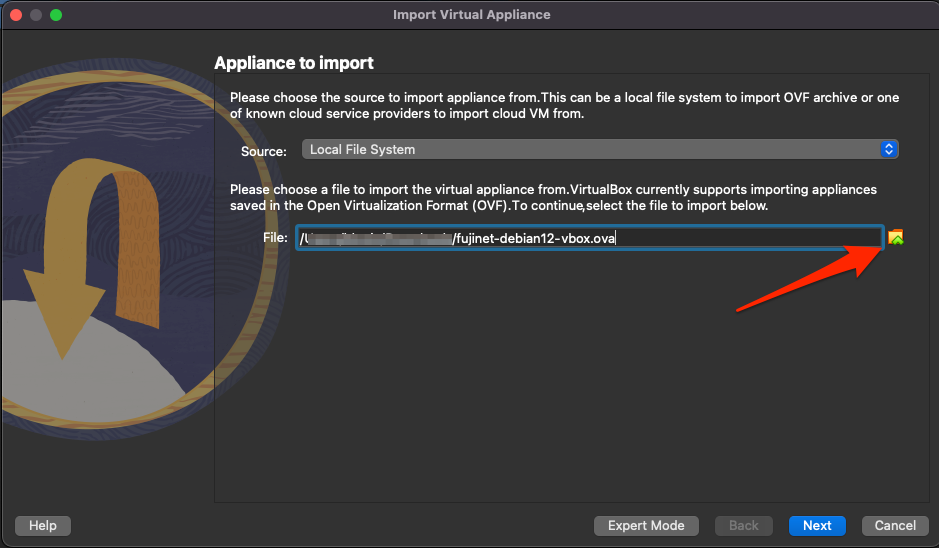
-
Optionally change the Machine Base Folder on the following page to where you’d like to store the imported VM. Most other items on this page are just informational & can be left as is.
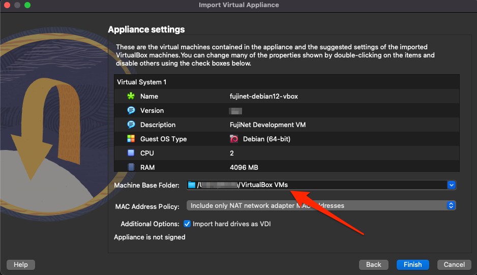
-
Click Finish & wait for the VM to be imported
Once the VM has been imported the various settings can be customized to your liking. However, the VM should work without any modifications. If more memory is available it will make a noticeable performance difference to increase the VM’s allotted RAM as much as possible.
Additional Documentation
Official FujiNet VirtualMachine documentation is available with more in-depth help & usage information.
Using FujiNet with Emulators
FujiNet can be used without any physical retro hardware by running it alongside emulators on modern computers. This page covers FujiNet-PC, the Altirra NetSIO bridge for Atari emulation, the FujiNet VirtualBox VM, and AppleWin integration for Apple II emulation.
Overview
graph TD
    subgraph "Virtualized FujiNet Stack"
        direction TB
        EMU[Atari/Apple Emulator] <-->|Custom Device<br/>or Direct Integration| BRIDGE[NetSIO Bridge<br/>netsio-hub.py]
        BRIDGE <-->|UDP Port 9997<br/>NetSIO Protocol| FNPC[FujiNet-PC]
        FNPC <-->|WiFi / Network| INET[Internet /<br/>FujiNet Services]
        FNPC <-->|HTTP| WEBUI[FujiNet Web UI<br/>Browser]
    end
| Component | Purpose |
|---|---|
| FujiNet-PC | Software implementation of FujiNet firmware running on a desktop/laptop |
| NetSIO Bridge | Python script that translates between emulator messages and NetSIO UDP datagrams |
| Emulator | Atari or Apple II emulator with FujiNet device support |
| Web UI | Browser-based configuration interface for the virtual FujiNet |
FujiNet-PC
FujiNet-PC is a software build of the FujiNet firmware that runs natively on Windows, macOS, and Linux. It replaces the ESP32 hardware with a standard computer while providing the same functionality: disk/cassette/printer emulation, network access, and the web configuration interface.
Downloads
- FujiNet-PC nightly builds: GitHub Releases (download the FujiNet-PC variant)
- NetSIO bridge scripts: fujinet-pc-launcher
Altirra + NetSIO Bridge (Atari)
The primary method for using FujiNet with Atari emulation is to connect the Altirra emulator to FujiNet-PC via the NetSIO bridge.
Data Flow
graph LR
    A[Altirra Emulator] <-->|netsio.atdevice<br/>Custom Device| B[NetSIO Bridge<br/>Python 3]
    B <-->|UDP 9997| C[FujiNet-PC]
    C <-->|Network| D[Internet]
Altirra uses a custom device file (netsio.atdevice) to communicate with the Python NetSIO bridge, which translates messages into NetSIO UDP datagrams for FujiNet-PC.
Requirements
| Dependency | Notes |
|---|---|
| Python 3 | Required for the NetSIO bridge |
| Altirra | Windows-only; use Wine on macOS/Linux |
| Wine (macOS/Linux only) | winehq.org |
Downloads
- Altirra – virtualdub.org/altirra.html
- NetSIO Bridge – fujinet-pc-launcher releases (download and unzip the
fujinet-pc-scripts-*archive) - FujiNet-PC – firmware releases (download the FujiNet-PC nightly build and extract to the
fujinet-pcdirectory from step 2)
Setup
Altirra Configuration
Configure Altirra for use with FujiNet:
- Disable fast boot so the FujiNet CONFIG program will boot:
"Kernel: Fast boot enabled" = 0 - Enable background execution so emulation continues when the window loses focus:
"Pause when inactive" = 0 - macOS only – disable Direct3D to avoid crashes under Wine:
"Display: Direct3D9" = 0 "Display: 3D" = 0 - Add the FujiNet device by pointing to the
netsio.atdevicefile in the Altirra custom devices configuration
Starting the Stack
-
Start the NetSIO bridge:
cd fujinet-pc-scripts/ python3 -m netsiohub --port 9996 --netsio-port 9997 -
Start FujiNet-PC:
cd fujinet-pc-scripts/fujinet-pc/ ./run-fujinet -
Start Altirra:
# Windows
Altirra64.exe /portablealt:instance-1.ini

# macOS/Linux with Wine
wine64 Altirra64.exe /portablealt:instance-1.ini
Altirra should boot into the FujiNet CONFIG screen.
Running Multiple Instances
It is possible to run two independent Altirra + FujiNet-PC instances on a single computer, simulating two separate Atari machines (useful for testing multiplayer games).
Port Configuration
| Instance | Bridge Port | NetSIO Port |
|---|---|---|
| Instance 1 | 9996 | 9997 |
| Instance 2 | 9986 | 9987 |
graph TD
    subgraph "Instance 1"
        A1[Altirra #1] <-->|netsio.atdevice<br/>port 9996| B1[Bridge #1]
        B1 <-->|UDP 9997| C1[FujiNet-PC #1]
    end
    subgraph "Instance 2"
        A2[Altirra #2] <-->|netsio-2.atdevice<br/>port 9986| B2[Bridge #2]
        B2 <-->|UDP 9987| C2[FujiNet-PC #2]
    end
    C1 & C2 <-->|Network| D[Internet]
Setup Steps
- Duplicate the fujinet-pc directory to
fujinet-pc2 - Edit
fujinet-pc2/fnconfig.ini– change the NetSIO port to9987:[NetSIO] enabled=1 host=localhost port=9987 - Duplicate
netsio.atdevicetonetsio-2.atdeviceand change the port to9986:option "network": { port: 9986 }; - Create two Altirra configurations (
instance-1.iniandinstance-2.ini), each pointing to its respective.atdevicefile - Launch all components:
# Bridges
python3 -m netsiohub --port 9996 --netsio-port 9997
python3 -m netsiohub --port 9986 --netsio-port 9987

# FujiNet-PC instances
cd fujinet-pc-scripts/fujinet-pc/ && ./run-fujinet
cd fujinet-pc-scripts/fujinet-pc2/ && ./run-fujinet

# Altirra instances
wine64 Altirra64.exe /portablealt:instance-1.ini
wine64 Altirra64.exe /portablealt:instance-2.ini
FujiNet Virtual Machine (VirtualBox)
The FujiNet VM is a pre-configured VirtualBox appliance that bundles everything needed to try FujiNet without purchasing any hardware.
VM Contents
| Component | Description |
|---|---|
| Operating System | Debian 12 Linux with XFCE 4 desktop |
| Altirra | Atari emulator, installed and run via Wine (desktop launcher) |
| AppleWin | Apple II emulator, native Linux port (desktop launcher) |
| FujiNet-PC (Atari) | With NetSIO bridge, starts automatically |
| FujiNet-PC (Apple) | For AppleWin integration, starts automatically |
| Epiphany | Web browser for accessing the FujiNet web UI |
Download and Import
- Download the latest VM build (~3.6 GB): FujiNet VM on MEGA
- Import into VirtualBox (version 6 or 7):
- From the File menu, select Import Appliance…
- Select the downloaded OVA file and click Next
- Optionally change the Machine Base Folder to your preferred storage location
- Click Finish and wait for the import to complete
Performance Tips
- Increase the VM’s allotted RAM as much as possible for noticeably better performance
- The VM works without any configuration changes after import
- All other VirtualBox settings can be customized to your preference
Additional Documentation
Detailed VM usage documentation is available at: fujinet-vm.readthedocs.io
AppleWin Integration (Apple II)
The FujiNet VM includes AppleWin (the native Linux port) pre-configured to connect to a virtual FujiNet-PC instance for Apple II emulation. FujiNet-PC for Apple starts automatically when the VM boots, and AppleWin can be launched from the desktop shortcut.
For standalone AppleWin + FujiNet-PC setup outside the VM, the process mirrors the Altirra setup: run FujiNet-PC configured for Apple II, then launch AppleWin with the appropriate FujiNet device configuration.
NetSIO Protocol Details
For the full technical specification of the NetSIO protocol used between the bridge and FujiNet-PC, see FEP 003: NetSIO Protocol.
See Also
- FEP 003: NetSIO Protocol – Full protocol specification
- FEP 004: FujiNet Protocol – Universal FujiNet packet format
- ESP32 Platform Details – Hardware used in physical FujiNet devices
- Official Hardware Versions – Physical FujiNet hardware revisions
Updating Firmware
The FujiNet device is a constantly evolving piece of hardware that can be upgraded with new features by flashing with new firmware when it becomes available. The pages in this section will provide details on where to find the latest firmware upgrades as well as how to go about flashing the device.
FujiNet Flasher
Table of Contents
- Overview
- How to find out when a new firmware version is available?
- Install the USB Driver
- Installing Firmware with FujiNet Flasher
- Capturing Serial Debug Output
- Tips for flashing problems
- Flashing a custom firmware file
- Creating a custom firmware file
- App and Code Signing the Macintosh Flasher
Overview
Occasionally, new versions of the FujiNet firmware (the software that runs on the FujiNet device itself) are released. The main FujiNet website has a page dedicated to the FujiNet Flasher tool, located here: https://fujinet.online/download/
How to find out when a new firmware version is available?
- Run the FujiNet-Flasher, select your Platform, select the version at the top of the list and compare the version information displayed to what you have installed on your FujiNet device
- mozzwald’s FujiNet Firmware Update Information thread at AtariAge for ATARI
- Maybe also the FujiNet User’s Group on Facebook
- Follow some key FujiNet developers on Twitter
Install the USB Driver
Some computers may not detect the FujiNet when it is plugged in. You may need to install the USB to UART driver from Silicon Labs (manufacturer of the chip used in Fujinet). Download and install the appropriate driver for your system.
Installing Firmware with FujiNet Flasher
The FujiNet Flasher tool will download the latest firmware, and upload it to your #FujiNet device.
Important
The flash tool only supports FujiNet hardware with 8MB PSRAM and 16MB flash for ATARI. Coleco ADAM FujiNet has support for 8MB and 16MB flash.
Windows
Run with administrator privileges
macOS
(Details needed.)
Linux
Run as root, e.g. sudo ./FujiNet-Flasher. Alternatively, add your ‘regular’ user to the appropriate ‘group’ on your system. For example, if your #FujiNet, via micro-USB cable, appears on your system as the device /dev/ttyUSB0, check which group the device is part of.
ls -l /dev/ttyUSB0
crw-rw---- 1 root dialout 188, 0 Nov 14 11:10 /dev/ttyUSB0
Then, add your account to that group (in the example above, “dialout”):
sudo usermod -a -G dialout USERNAME
To access it immediately (no need to log out and back in) just run, e.g., newgrp dialout.
Now, you should be able to run ./FujiNet-Flasher without switching to root user, or running it under sudo.
Capturing Serial Debug Output
Debugging info from FujiNet can be captured using Fujinet-Flasher. This info may be requested by developers to aid in fixing bugs or troubleshooting hardware problems. These are the steps to capture this information:
- Connect FujiNet to a computer with a MicroUSB cable
- Run Fujinet-Flasher and select the the correct port used by Fujinet (ie, COM3 on Windows, /dev/ttyUSB0 on linux)
- Click the Serial Debug Output button in Fujinet-Flasher
- Press the RESET button on the FujiNet device (Button C, far right)
- Debug information will appear in the Fujinet-Flasher window
- Reproduce your problem with FujiNet then select all (CTRL-A) text in the box and copy it (CTRL-C)
- Paste the debug output to the developer requesting this information
- If using AtariAge forum, paste the information into a Spoiler box so the debug output does not fill up the thread
- Optionally, use a paste site such as our FujiNet PrivateBin and provide the URL
Tips for flashing problems
Some people have issues where the flasher just shows Connecting...---... or similar when trying to flash the FujiNet. Sometimes this can be caused by a poor quality USB cable and can be fixed by trying another. If the problem persists, you can also force the FujiNet into flashing mode by pressing and holding down the A Button during the entire flashing process. (More info about the flashing issue in this “espressif/esptool” bug report comment.)
A user has provided this process for Windows users having issues. The issue appears to be that some other app or program takes control of the serial port if you wait too long:
- Run FujiNet-Flasher
- Select your platform
- Select firmware version
- Turn on or plugin the FujiNet and quickly hit the Flash Firmware button
Flashing a custom firmware file
Sometimes the FujiNet development team may provide a custom firmware file (ZIP) to an end user for testing. This file can be flashed with FujiNet-Flasher. Previously, one had to run the flasher from the command line (FujiNet-Flasher /path/to/firmware.zip) to use a custom firmware file. The latest version has an option in the interface to select a local firmware file to flash.
Download the latest version at Fujinet Home
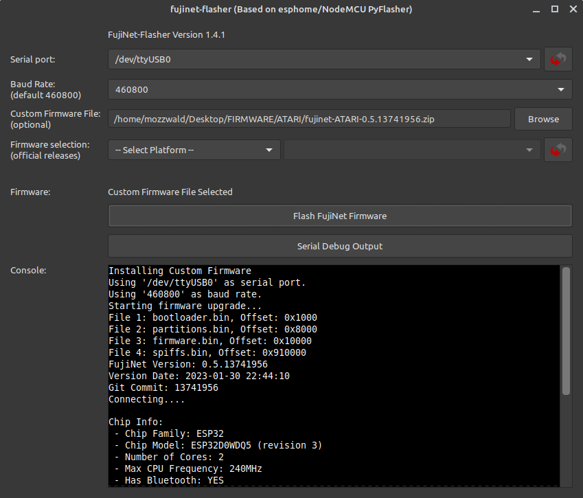
Creating a custom firmware file
A new script has been added to the fujinet-platformio repo that can be enabled in platformio.ini which will build a flashable firmware ZIP file. First, you must uncomment the post build script below (remove the semicolon at the beginning of the line):
extra_scripts =
    pre:build_packages.py
    pre:build_version.py
    pre:build_webui.py
    ;post:build_firmwarezip.py ; Optional, build firmware ZIP file for flash tool
You can also optionally have the script rename the firmware file. By default the name is based on platform (your chosen hardware platform) and version number (from include/version.h). To change the name, uncomment the line below in platformio.ini and modify it to your needs:
; Override platform name when creating firmware ZIP file
; ex: fujinet-CUSTOMNAME-v1.0.zip
;platform_name = CUSTOMNAME
After saving the settings to platformio.ini, you must first run the Project Tasks Build Filesystem Image and then Build the firmware. If the build is successful, you will see a new firmware dir in the fujinet-platformio repo dir that contains the flashable ZIP file.
Note
Manual Firmware File Creation
Some users may wish to build their own firmware file for distribution (ie, custom hardware builds, special unsupported features, etc).
Create a new directory for the firmware files to reside and edit a new text file named
release.jsonin that directory.Edit the
release.jsonfile accordingly for your target board. For an 8MB variant board:{ "version": "NEW VERSION NUMBER", "version_date": "VERSION DATE/TIME, format: 2023-01-01 12:59:59", "build_date": "BUILD DATE/TIME, format: 2023-01-01 12:59:59", "description": "NOTES AND DESCRIPTION OF THE CHANGES", "git_commit": "GIT COMMIT HASH", "files": [ { "filename": "bootloader.bin", "offset": "0x1000" }, { "filename": "partitions.bin", "offset": "0x8000" }, { "filename": "firmware.bin", "offset": "0x10000" }, { "filename": "spiffs.bin", "offset": "0x600000" } ] }For a 16MB variant board:
{
  "version": "NEW VERSION NUMBER",
  "version_date": "VERSION DATE/TIME, format: 2023-01-01 12:59:59",
  "build_date": "BUILD DATE/TIME, format: 2023-01-01 12:59:59",
  "description": "NOTES AND DESCRIPTION OF THE CHANGES",
  "git_commit": "GIT COMMIT HASH",
  "files": [
    {
      "filename": "bootloader.bin",
      "offset": "0x1000"
    },
    {
      "filename": "partitions.bin",
      "offset": "0x8000"
    },
    {
      "filename": "firmware.bin",
      "offset": "0x10000"
    },
    {
      "filename": "spiffs.bin",
      "offset": "0x910000"
    }
  ]
}
Using PlatformIO and VSCode, build the Firmware and Filesystem images
Copy the firmware files (
bootloader.bin,partitions.bin,firmware.binandspiffs.bin) fromfujinet-platformio/.pio/build/(target-platform)/to the same directory withrelease.jsonCompress the files into the root of a ZIP file (not in a subfolder) and provide it to the end user
App and Code Signing the Macintosh Flasher
In order to not have a modern Mac (OSX) refuse to allow you to run the Flasher.app when you first download and run it- it should be code signed and app notorized with Apple. This requires a paid apple Dev account.
Andy Diller has one and has signed the 10.5 release. Below are directions if anyone in the future or present would like to sign their own build for some reason. You would have already setup your Dev account, made a Team, created an app and app password.
Step 1
Get the Build Flasher.zip from Mozzwald. This is aleady in the right structure to sign and then zip back up. The commands below assume you have taken the zip from Moz and simply unzipped it into it’s own directory. Remove the original zip file as you will creating a new one.
Step 2
Follow the below commands. They should make some sense if you know what you are doing. If they do not make sense then ask a friend or use one that is already signed.
Commands
export SIGN_ID="Developer ID Application: YOUR NAME (YOUR ID)"
export APP_PATH="/Users/sjobs/flasher-sign/15/FujiNet-Flasher.app"

codesign --force --timestamp --options runtime --sign "$SIGN_ID" "$APP_PATH/Contents/MacOS/FujiNet-Flasher"
codesign --force --deep --options runtime --timestamp --sign "$SIGN_ID" "$APP_PATH"
codesign --verify --deep --strict --verbose=2 "$APP_PATH"

ditto -c -k --keepParent FujiNet-Flasher.app FujiNet-Flasher_v1.5.0_macos-10.15.zip

xcrun notarytool submit FujiNet-Flasher_v1.5.0_macos-10.15.zip \
  --apple-id "YOUR_ID" \
  --team-id "YOUR_TEAM_ID" \
  --password "APP_PW_YOU_CREATED_FOR_TEAM" \
  --wait

xcrun stapler staple "$APP_PATH"

spctl --assess --type exec --verbose=4 "$APP_PATH"
You are done. You can take that new ZIP and it should install on other’s Mac’s without requiring them to go into Pref/Security and “Run Anyway” etc. etc. etc…
Nightly Firmware Builds
Every night an automated GitHub Action is triggered to build the FujiNet Firmware for multiple platforms that are in a working state currently. If successful, the resulting firmware ZIP file is attached to a permanent special GitHub Pre-Release called Nightly Builds.
If you wish to try the bleeding edge current state of the fujinet-firmware code but don’t have a build environment of your own then this is the place to go! Download the appropriate file to your local computer & use the Fujinet Flasher tool to flash your FujiNet device with this custom-built ZIP file.
Warning
There is NO guarantee that these builds work!!
These builds are NOT official builds & are provided 100% AS-IS with absolutely no guarantee that they will work. Only use these builds if you know what you are doing & are willing to troubleshoot any problems on your own.
Of course reporting any bugs you run across would be greatly appreciated but they should be accompanied by console logs & any other appropriate details that might help in troubleshooting the issues. Generally the FujiNet Discord is the best place to discuss any issues you find in these builds.
Developer Documentation
Theory of Operation
Creating a FujiNet Application
FujiNet-Lib
Developing FujiNet
Setting Up the Build Environment
This guide covers everything needed to prepare your development machine for building FujiNet firmware. Whether you plan to use an IDE or work entirely from the command line, these steps will get you up and running.
Supported Operating Systems
| OS | Notes |
|---|---|
| Linux (Ubuntu, Debian, etc.) | Recommended. Native support. |
| macOS (Intel and Apple Silicon) | Fully supported. |
| Windows (via WSL) | Install WSL/WSL2 from the Microsoft Store. Building on raw Windows is not recommended. |
Prerequisites
System Packages (Linux / WSL)
Update your system and install the required packages:
sudo apt update && sudo apt upgrade
sudo apt install git curl python3-venv cmake build-essential \
    libmbedtls-dev libexpat1-dev pip -y
For FujiNet-PC builds, you will also need:
sudo apt install libpython3-dev
sudo pip install Jinja2
USB Permissions (Linux / WSL)
To flash firmware over USB, your user account must be in the dialout group:
sudo adduser $(whoami) dialout
newgrp dialout
A reboot is required for the group change to take full effect.
Python
PlatformIO requires Python 3. Most modern Linux and macOS systems ship with Python 3 already installed. Verify with:
python3 --version
Installing PlatformIO Core (CLI)
PlatformIO (PIO) is the build system used for FujiNet firmware. It should always be installed in your home directory.
-
Download the installer:
cd ~ curl -fsSL -o get-platformio.py \ https://raw.githubusercontent.com/platformio/platformio-core-installer/master/get-platformio.py -
Run the installer:
python3 ./get-platformio.py -
Add PIO to your PATH:
export PATH=$PATH:~/.platformio/penv/binTo make this permanent, add it to your shell profile:
echo 'export PATH=$PATH:~/.platformio/penv/bin' >> ~/.bashrc -
Install the ESP32 platform:
pio platform install espressif32
VS Code + PlatformIO IDE (Optional)
If you prefer a graphical IDE, Visual Studio Code with the PlatformIO extension provides an integrated experience:
- Install Visual Studio Code.
- Open the Extensions panel (
Ctrl+Shift+X) and search for PlatformIO IDE. - Install the extension and restart VS Code.
- PlatformIO will automatically detect the FujiNet project when you open the repository folder.
Note: If you use both the CLI and VS Code, avoid running them simultaneously as there will be file contention between the two.
Verifying the Installation
After installation, confirm PlatformIO is available:
pio --version
You should see output similar to:
PlatformIO Core, version 6.x.x
Environment Overview
graph TD
    A[Development Machine] --> B{Choose Workflow}
    B --> C[VS Code + PIO Extension]
    B --> D[CLI with build.sh]
    C --> E[PlatformIO Core]
    D --> E
    E --> F[ESP-IDF / Espressif32 Toolchain]
    F --> G[Build & Flash FujiNet]
Next Steps
- Building Firmware – clone the repository and compile firmware for your target platform.
- Building FujiNet-PC – build the desktop/POSIX version of FujiNet.
- Firmware Versioning – understand the version numbering scheme.
Building FujiNet Firmware
This guide walks through cloning the FujiNet firmware repository, selecting a target platform, building the firmware, flashing it to hardware, and monitoring output. It assumes you have already completed the build environment setup.
Build Process Overview
flowchart TD
    A[Clone Repository] --> B[Select Platform Target]
    B --> C[Generate platformio.local.ini]
    C --> D[Customize Local Settings]
    D --> E{Build Method}
    E --> F["build.sh -b (CLI)"]
    E --> G[VS Code PIO Build]
    F --> H[Compile Firmware]
    G --> H
    H --> I{Success?}
    I -->|Yes| J[Flash to Device]
    I -->|No| K[Fix Errors & Rebuild]
    K --> H
    J --> L[Flash Filesystem / WebUI]
    L --> M[Monitor Serial Output]
Cloning the Repository
Clone vs. Fork
- Clone directly if you only want to build and use the firmware.
- Fork first if you plan to modify code and contribute changes via pull requests.
mkdir -p ~/code && cd ~/code
git clone https://github.com/FujiNetWIFI/fujinet-firmware.git
cd fujinet-firmware
Selecting a Platform Target
The build.sh script manages platform configuration files so that multiple targets can coexist without interfering with each other.
List Available Boards
Run build.sh without arguments to see all supported boards:
./build.sh
The output lists supported boards at the bottom. Current boards include:
| Board INI | Platform |
|---|---|
fujinet-atari-v1 | Atari 8-bit |
fujiapple-rev0 | Apple II |
fujinet-adam-v1 | Coleco ADAM |
fujinet-coco-lolin-d32-dw | Tandy CoCo |
fujinet-v1-8mb | FujiNet v1 (8MB flash) |
fujinet-iec-nugget | Commodore IEC (Nugget) |
fujinet-cx16 | Commander X16 |
fujinet-heathkit-h89 | Heathkit H89 |
fujinet-lynx-prototype | Atari Lynx |
fujinet-rc2014spi-rev0 | RC2014 SPI |
fujinet-rs232-rev0 | RS-232 |
fujinet-s100-v1-8mb | S-100 Bus |
Set Up a Board
Use the -s flag with the board name (drop the platformio- prefix and .ini suffix):
./build.sh -s fujinet-atari-v1
You will be prompted to confirm. This creates platformio.local.ini with the selected board configuration.
Platform Configuration (platformio.local.ini)
After setup, you may need to edit platformio.local.ini to set your USB serial device:
-
Linux: Typically
/dev/ttyUSB0(the default). -
macOS: Something like
/dev/cu.usbserial-XXXXX. Find it with:ls /dev/tty* | grep usb -
WSL: USB passthrough to WSL requires additional setup. See the FujiNet USB-WSL video guide.
Important: Do not manually create
platformio.iniusingpio project init. Letbuild.shhandle configuration file generation.
Using build.sh
The build.sh script is the primary build tool. Here is the full set of options:
Usage: build.sh [-b|-e ENV|-c|-m|-x|-t TARGET|-h]
   -b       # run build
   -c       # run clean before build
   -d       # add dev flag to build
   -m       # run monitor after build
   -u       # upload image (device code)
   -f       # upload filesystem (webUI etc)
   -x       # exclude dep graph output from logging
   -e ENV   # use specific environment
   -t TGT   # run target task
   -s NAME  # setup a new board
   -a       # build all platforms
   -h       # this help
Common Build Commands
| Command | Description |
|---|---|
./build.sh -b | Build firmware only (no flash). Good as a first test. |
./build.sh -um | Build, flash firmware, and start serial monitor. |
./build.sh -fum | Build, flash firmware + filesystem (WebUI), and monitor. |
./build.sh -cb | Clean and rebuild from scratch. |
./build.sh -a | Build all platforms. Results written to build-results.txt. |
Build and Flash Example
A typical development cycle:
# Ensure PIO is in PATH
export PATH=$PATH:~/.platformio/penv/bin

# Build, flash, and monitor
./build.sh -um
PlatformIO detects changed files automatically and only recompiles what is necessary.
Serial Monitor
You can monitor the FujiNet serial output independently of building:
pio device monitor -b 460800 -p /dev/ttyUSB0
Replace /dev/ttyUSB0 with your actual device path. The baud rate for FujiNet is 460800.
The serial monitor provides real-time debug output from the running firmware, which is invaluable during development.
Build All Platforms
To verify that your changes compile across every supported platform:
./build.sh -a
This produces a build-results.txt file in the repository root with timestamps and success/failure status for each platform.
Nightly Builds
Pre-built nightly firmware images from the master branch are available at:
https://github.com/FujiNetWIFI/fujinet-firmware/releases/tag/nightly
Troubleshooting
| Problem | Solution |
|---|---|
NotPlatformIOProjectError | Run ./build.sh -s <board> to generate the INI file. Do not run pio project init. |
| USB device not found | Check your platformio.local.ini serial port setting. On Linux, ensure your user is in the dialout group. |
| Build contention errors | Do not run VS Code with PIO and build.sh simultaneously. Also avoid running FujiNet Flasher at the same time. |
Next Steps
- Building FujiNet-PC – build the desktop version for use with emulators.
- Firmware Versioning – understand how version numbers are managed.
- Build Environment Setup – revisit prerequisite installation.
Building FujiNet-PC
FujiNet-PC is the POSIX/desktop implementation of FujiNet. It runs on Linux, macOS, and Windows (via WSL), providing the full FujiNet experience without any hardware. Combined with a platform emulator such as Altirra (Atari) or AppleWin (Apple II), it creates a complete virtual retro computing environment.
As of 2024, the FujiNet-PC codebase is integrated into the main fujinet-firmware repository. The same build.sh script handles both firmware and FujiNet-PC builds.
Architecture Overview
flowchart LR
    subgraph Desktop Machine
        A[Platform Emulator<br>Altirra / AppleWin] <-->|Bridge Protocol<br>netsio / SmartPort| B[FujiNet-PC]
        B <--> C[Network / SD / Config]
        D[Web Browser] -->|WebUI| B
    end
Dependencies
Linux / WSL
Install the required packages:
sudo apt update && sudo apt upgrade
sudo apt install git curl build-essential cmake \
    libpython3-dev python3-venv libmbedtls-dev pip -y
sudo pip install Jinja2
macOS
Ensure you have Xcode command line tools, CMake, and Python 3 installed:
xcode-select --install
brew install cmake python3 mbedtls
pip3 install Jinja2
Building FujiNet-PC
FujiNet-PC is built using the -p flag with build.sh. You must specify the target platform (the retro computer being emulated).
Build for Atari
cd ~/code/fujinet-firmware
./build.sh -cp ATARI
Build for Apple II
./build.sh -cp APPLE
The -c flag triggers a clean build (recommended for the first build). Subsequent builds can omit it:
./build.sh -p ATARI
Build Output
A successful build produces output similar to:
[100%] Built target fujinet
[100%] Preparing dist directory
[100%] Built target dist
Built PC version in build/dist folder
The compiled application and all required files are placed in the build/dist directory.
Running FujiNet-PC
cd build/dist
./run-fujinet
You should see startup output like:
Starting FujiNet
14:46:46.292954 >
14:46:46.296816 > --~--~--~--
14:46:46.296857 > FujiNet v1.3 2024-04-26 06:08:28 Started
14:46:46.296910 > Detected Hardware Version: fujinet-pc
14:46:46.296944 > SPIFFS mounted.
14:46:46.298056 > SD mounted (directory "SD").
Once running, access the FujiNet WebUI by opening a browser to:
http://localhost:8000
Using with Emulators
Altirra (Atari)
FujiNet-PC for Atari uses the netsio bridge to connect to Altirra. On Linux, Altirra runs via Wine.
- Start FujiNet-PC (it listens for
netsioconnections automatically). - Launch Altirra.
- In Altirra, configure the SIO device to use the network SIO bridge.
AppleWin (Apple II)
FujiNet-PC for Apple II connects directly to AppleWin (a native Linux port is available).
- Start FujiNet-PC for Apple.
- Launch AppleWin.
- Configure AppleWin to use the FujiNet SmartPort device.
FujiNet Virtual Machine
For the easiest way to try FujiNet-PC without manual setup, a pre-built VirtualBox appliance is available. The FujiNet Virtual Machine includes:
- Debian 12 Linux with XFCE 4 desktop
- Altirra (via Wine) and AppleWin (native Linux port)
- FujiNet-PC pre-configured for both Atari and Apple II
netsiobridge for Altirra connectivity- Epiphany web browser for WebUI access
Download the VM appliance (~3.6 GB): https://mega.nz/folder/4L03hKRL#L1GOblpv8xbHROaKIPb1xg
For detailed VM usage instructions, see the official FujiNet VM documentation.
FujiNet-PC Build Process
flowchart TD
    A[Clone fujinet-firmware repo] --> B["build.sh -cp PLATFORM"]
    B --> C[CMake generates build system]
    C --> D[Compile FujiNet-PC]
    D --> E[Prepare dist directory]
    E --> F[build/dist/run-fujinet]
    F --> G{Platform?}
    G -->|ATARI| H[netsio bridge to Altirra]
    G -->|APPLE| I[SmartPort bridge to AppleWin]
Troubleshooting
| Problem | Solution |
|---|---|
Missing cmake or build tools | Install the full set of dependencies for your OS. |
Jinja2 module not found | Run sudo pip install Jinja2. |
| Cannot connect emulator to FujiNet-PC | Ensure FujiNet-PC is running before launching the emulator. Check that no firewall rules block localhost connections. |
| WSL USB passthrough issues | See the USB-WSL video guide for setup instructions. |
Next Steps
- Build Environment Setup – prerequisite installation details.
- Building Firmware – building firmware for physical FujiNet hardware.
- Firmware Versioning – how FujiNet version numbers work.
Firmware Versioning
FujiNet uses a manual versioning scheme maintained by developers in the source code. This document describes the version format, when to change version numbers, and the process for creating a release build.
Version Format
FujiNet firmware versions follow a three-part numeric format:
vMAJOR.MINOR.BUILD
For example: v1.3.0
| Component | Purpose | When to Increment |
|---|---|---|
| MAJOR | Significant architectural changes or breaking updates | Major rewrites, protocol changes, or backward-incompatible modifications |
| MINOR | New features or notable improvements | New device support, new protocol features, significant enhancements |
| BUILD | Bug fixes and minor patches | Bug fixes, small tweaks, documentation updates within the firmware |
Version File Location
The version is defined in:
fujinet-firmware/include/version.h
This file is manually edited by developers when preparing a new release. It contains the version string and version date/time that are compiled into the firmware binary.
Version Lifecycle
flowchart TD
    A[Development on master branch] --> B[Changes accumulate]
    B --> C{Ready for release?}
    C -->|No| A
    C -->|Yes| D[Update include/version.h]
    D --> E[Commit version change to master]
    E --> F[Verify all platforms build]
    F --> G[Test on released platforms]
    G --> H["Checkout release branch"]
    H --> I[Merge master into release]
    I --> J["Create annotated tag (vX.Y.Z)"]
    J --> K[Push tag to origin]
    K --> L[CI builds & publishes release]
Release Process
When the team decides it is time to cut a new release, the following steps must be completed in order:
-
Verify all platforms build – Check GitHub Actions to confirm the
masterbranch builds successfully for all supported platforms. -
Ensure CONFIG binary is current – The latest CONFIG binary must be pushed into all platforms on
master. -
Test on released platforms – Verify that all officially released platforms can boot and use the firmware built from
master. As of the latest guidance, the officially released platforms include Atari, Apple II, and ADAM. -
Update
version.h– Editinclude/version.hin themasterbranch with the new version number and version date/time. Commit this change. -
Merge to release branch:
git checkout release git merge master -
Create an annotated tag:
git tag -a v1.3.0 -m "Short and sweet release description"The tag description is displayed to end users and should be a succinct summary of the most important changes.
-
Push the tag:
git push origin v1.3.0Any tag beginning with
vtriggers the CI release build pipeline.
Release Tags and Changelogs
When a tag in the form vXX.XX.XX is pushed, the build system:
- Triggers automated release builds for all supported platforms.
- Generates a changelog containing a bulleted list of commit messages since the previous release.
Because the changelog is automatically generated from commit messages, it is important that developers write clear, descriptive commit messages. Messages such as “Tweaks” or “Fix stuff” should be avoided.
Commit Message Guidelines
Since commit messages feed directly into the release changelog, follow these practices:
| Do | Do Not |
|---|---|
Add ADAM printer support | Tweaks |
Fix SIO timing for PAL systems | Fix bug |
Update WebUI to show firmware version | Changes |
Refactor network device initialization | WIP |
Nightly Builds
In addition to tagged releases, nightly builds are automatically generated from the master branch and published at:
https://github.com/FujiNetWIFI/fujinet-firmware/releases/tag/nightly
These provide the latest development firmware for testing but are not considered stable releases.
Next Steps
- Building Firmware – build the firmware from source.
- Build Environment Setup – set up your development toolchain.
- Building FujiNet-PC – build the desktop version.
Atari Programming Overview
Programming the FujiNet on the Atari 8-bit platform revolves around the SIO (Serial Input/Output) bus, the same communication layer used by disk drives, printers, and modems. The FujiNet appears as one or more SIO devices, and programs interact with it through the Atari’s standard CIO (Central I/O) subsystem or directly via SIO calls.
Architecture
The Atari’s I/O stack is layered. User programs issue CIO calls, which the operating system translates into low-level SIO bus transactions. The FujiNet N: device handler (loaded at boot or from the CONFIG program) sits in this stack and translates CIO operations into the appropriate SIO commands for the FujiNet hardware.
graph TD
    A["User Program<br/>(BASIC / Assembly / cc65)"] -->|"CIO Calls<br/>OPEN, GET, PUT, XIO"| B["Atari OS CIO Subsystem"]
    B -->|"Device Handler Dispatch"| C["N: Device Handler<br/>(FujiNet Handler in RAM)"]
    C -->|"SIO Bus Commands"| D["FujiNet Hardware<br/>(ESP32 on SIO Bus)"]
    D -->|"Network Protocols<br/>HTTP, TCP, UDP, etc."| E["Internet / Network"]

    style A fill:#4a90d9,color:#fff
    style B fill:#7b68ee,color:#fff
    style C fill:#e07020,color:#fff
    style D fill:#d94040,color:#fff
    style E fill:#50a050,color:#fff
Device IDs
The FujiNet uses the following SIO device IDs:
| Device ID | Purpose |
|---|---|
$70 | FujiNet Control Device – adapter configuration, WiFi management, host/device slot operations, clock, app keys, and other system-level functions |
$71 - $78 | N: Network Devices – up to eight simultaneous network connections, each supporting protocols such as HTTP, HTTPS, TCP, UDP, FTP, TNFS, SMB, and more |
The FujiNet also emulates standard Atari SIO devices (disk drives at $31-$38, printers, RS-232, etc.), but the $70 control device and $71-$78 network devices are unique to FujiNet.
Programming Approaches
Atari BASIC
The most accessible way to use the FujiNet is through Atari BASIC using OPEN, PRINT#, INPUT#, GET#, and XIO commands with the N: device. The N: handler must be loaded first (it loads automatically when booting from FujiNet CONFIG).
Quick Start – Reading a Mastodon Post:
0 DIM A$(256)
1 TRAP 91
2 POKE 756,204
10 OPEN #1,12,0,"N:HTTPS://OLDBYTES.SPACE/api/v1/timelines/public?limit=1"
20 XIO 252,#1,12,1,"N:":REM SET CHANNEL MODE TO JSON
30 XIO ASC("P"),#1,12,0,"N:":REM PARSE THE JSON
40 XIO ASC("Q"),#1,12,3,"N:/0/account/display_name"
50 INPUT #1,A$:? A$
60 XIO ASC("Q"),#1,12,3,"N:/0/created_at"
70 INPUT #1,A$:? A$
80 XIO ASC("Q"),#1,12,3,"N:/0/content"
90 GET #1,A:? CHR$(A);:GOTO 90
91 CLOSE #1:? :?
100 POKE 18,0:POKE 19,0:POKE 20,0
110 IF PEEK(19)<30 THEN 110
120 GOTO 1
This example opens an HTTPS connection, switches the channel to JSON mode, parses the response, queries specific JSON fields, and prints the results.
Assembly Language
For maximum performance and control, programmers can issue SIO calls directly from 6502 assembly. This bypasses CIO overhead and communicates with FujiNet device IDs $70-$78 at the bus level. The SIO command frame specifies the device ID, command byte, auxiliary bytes, buffer address, and transfer length.
cc65 (C Cross-Compiler)
The cc65 cross-compiler for 6502 targets provides a practical middle ground. The fujinet-lib project offers a C library that wraps the SIO interface, making FujiNet programming accessible from C while retaining good performance.
CIO Commands
The N: device handler implements the following standard CIO commands, allowing BASIC and other high-level languages to perform network I/O as if it were file I/O:
| CIO Command | Operation |
|---|---|
OPEN ($03) | Open a network connection using a URL |
GET RECORD ($05) | Read a line of text (up to EOL) |
GET CHARACTERS ($07) | Read a specified number of bytes |
PUT RECORD ($09) | Write a line of text with EOL |
PUT CHARACTERS ($0B) | Write a specified number of bytes |
CLOSE ($0C) | Close the network connection |
STATUS ($0D) | Get connection status and bytes waiting |
XIO Commands
The XIO statement provides access to extended operations beyond standard CIO:
| XIO Command | Description |
|---|---|
$0F | Flush write buffer – forces buffered data to the network |
$41 ('A') | Accept a pending TCP client connection |
$FC (252) | Set channel mode (e.g., JSON mode) |
$50 ('P') | Parse JSON data |
$51 ('Q') | Query a JSON element by path |
$FF | Reset FujiNet |
XIO Syntax in BASIC:
XIO command,#iocb,aux1,aux2,"N:"
Where command is the XIO code, #iocb is the I/O channel (1-7), and aux1/aux2 provide additional parameters.
SIO Command Reference
For low-level programming (assembly, cc65, or advanced BASIC using USR routines), the full SIO command tables are essential references:
- Device
$70(FujiNet Control) – WiFi management, host/device slots, clock, app keys, boot mode, hashing, Base64, QR codes, and more. See the SIO Commands for Device $70 reference. - Devices
$71-$78(N: Network) – Open, Close, Read, Write, Status, JSON parse/query, channel mode, login/password, file operations, and protocol-specific commands. See the SIO Commands for Devices $71-$78 reference.
URL Format
All N: device URLs follow this format:
N:PROTO://[HOSTNAME][:PORT]/[PATH]
Where:
- PROTO is the protocol (
HTTP,HTTPS,TCP,UDP,TNFS,FTP,SMB,SSH, etc.) - HOSTNAME is the destination host (can be omitted for listening sockets)
- PORT is the port number (optional for most protocols, required for listening sockets)
- PATH is the resource path (optional)
Further Reading
- Using HTTP/S from BASIC
- Atari BASIC JSON POST Best Practices
- N: Game Developer Cheat Sheet
- Error Codes for N: Device
Apple II Programming Overview
All communication with the FujiNet on the Apple II platform is performed through the SmartPort interface. SmartPort is Apple’s block-device protocol for intelligent peripherals, and the FujiNet uses it to expose multiple virtual devices – disk images, network adapters, a printer, and the FujiNet control device itself.
SmartPort Fundamentals
Before issuing any FujiNet commands, your program must:
- Find the SmartPort slot by scanning the I/O ROM space
- Locate the dispatcher address within that slot
- Enumerate devices to find the one you need (FUJI, NETWORK, etc.)
Finding the SmartPort Slot
Scan each slot’s ROM space ($C100-$C700) for the SmartPort signature bytes at offsets 1, 3, 5, and 7:
| Offset | Expected Byte |
|---|---|
| 1 | $20 |
| 3 | $00 |
| 5 | $03 |
| 7 | $00 |
C implementation (cc65):
uint8_t sp_find_slot(void)
{
    uint8_t s = 0;
    for (s = 7; s-- > 0;)
    {
        uint16_t a = 0xC000 + (s * 0x100);
        if ((PEEK(a+1) == 0x20) &&
            (PEEK(a+3) == 0x00) &&
            (PEEK(a+5) == 0x03) &&
            (PEEK(a+7) == 0x00))
            return s;
    }
    return 0; // Not found
}
Finding the Dispatch Address
Once the slot is found, read the byte at offset $FF in the slot ROM, add 3 to it, and add the result to the slot base address:
uint16_t sp_dispatch_address(uint8_t slot)
{
    uint16_t a = (slot * 0x100) + 0xC000;
    uint8_t j = PEEK(a + 0xFF);
    return a + j + 3;
}
Finding SmartPort Devices
With the dispatcher located, enumerate devices using STATUS command $00 to get the device count, then iterate through each device issuing STATUS command $03 (Get DIB) to read each device’s type string.
int8_t sp_find_network(void)
{
    const char net[7] = "NETWORK";
    const uint8_t net_len = sizeof(net);
    int8_t err, num, i, j;

    err = sp_status(0x00, 0x00); // Get number of devices
    if (err) return -err;

    num = sp_payload[0];
    num += 2;

    for (i = 1; i < num; i++)
    {
        err = sp_status(i, 0x03); // Get DIB
        if (sp_payload[4] == net_len)
        {
            for (j = 0; j < net_len; j++)
                if (net[j] != sp_payload[5+j])
                    return 0;
            return i;
        }
    }
    return 0; // Not found
}
Issuing SmartPort Commands
The FujiNet responds to four SmartPort command types:
| Command | Code | Purpose | Parameter Count |
|---|---|---|---|
| STATUS | $00 | Request information from a device | 3 |
| CONTROL | $04 | Send an imperative command to a device | 3 |
| READ | $08 | Read bytes from a device into a buffer | 4 |
| WRITE | $09 | Write bytes from a buffer to a device | 4 |
All commands are issued by calling the dispatcher with a command code followed by a pointer to a parameter list:
    JSR DISPATCH
    DFB #STATUSCODE      ; Command code
    DW  CMDLIST           ; Pointer to parameter list
    BCS ERROR             ; Carry set on error
The parameter list for STATUS and CONTROL:
CMDLIST:
    DFB #$03             ; Parameter count (3)
    DFB #DEST            ; Destination device number
    DW  BUFFER           ; Buffer address (lo/hi)
    DFB STATUSCODE       ; Status or control code
READ and WRITE add a two-byte buffer length:
CMDLIST:
    DFB #$04             ; Parameter count (4)
    DFB #DEST            ; Destination device number
    DW  BUFFER           ; Buffer address (lo/hi)
    DW  LEN              ; Number of bytes to transfer
FujiNet Device Types
The FujiNet exposes several virtual SmartPort devices. The exact list depends on configuration, but typically includes:
| Device Name | Description |
|---|---|
FUJINET_DISK_0 … FUJINET_DISK_n | Virtual disk drives for mounting disk images |
NETWORK (or NETWORK_0) | First network device for protocol-based I/O |
NETWORK_1 … NETWORK_3 | Additional network devices (up to 4 total) |
FN_PRINTER | Virtual printer device |
FN_CPM | CP/M emulation device |
THE_FUJI | FujiNet control device for system-level operations |
Note: SmartPort unit numbers do not necessarily correspond to logical device numbers used in BASIC. Use device enumeration to find the correct unit for each device type.
Applesoft BASIC Network Extensions
For Applesoft BASIC programmers, FujiNet provides ampersand (&) extensions that simplify network programming. These must be loaded into memory before use.
Loading the Extensions
REM Check if extensions are already loaded, otherwise load them
10000 GOSUB 10030: IF R=1 THEN PRINT "EXTENSIONS ALREADY INSTALLED.": RETURN
10010 PRINT "LOADING EXTENSIONS..."
10020 PRINT CHR$(4);"BLOAD /FUJI.APPLE/FUJIAPPLE":CALL 16384:RETURN
Available Ampersand Commands
| Command | Description |
|---|---|
&NOPEN unit, mode, trans, url$ | Open a network URL |
&NCLOSE unit | Close a network connection |
&NSTATUS unit, bw, connected, nerr | Get connection status |
&NREAD unit, var$, len | Read bytes into a string variable |
&NWRITE unit, var$, len | Write bytes from a string variable |
&NPRINT unit, var$[;] | Send a string (with optional EOL suppression) |
&NINPUT unit, var$ | Receive a line of text |
&NJSON unit, onoff | Enable or disable JSON channel mode |
&NQUERY unit, query$, value$ | Query a JSON element by path |
&NCTRL unit, command$, payload$ | Send a control command |
&NACCEPT unit | Accept an incoming TCP connection |
&NLIST [var$] | List SmartPort devices (or store list in variable) |
&NSETEOL [eol] | Set end-of-line character |
&NTIME yr, mo, dy, hr, mn, s | Get current time from FujiNet |
NOPEN Mode Values
| Mode | Description |
|---|---|
| 4 | Read only (e.g., HTTP GET) |
| 6 | Read directory listing |
| 8 | Write only (e.g., HTTP PUT) |
| 12 | Read and write (typical for TCP/UDP) |
| 13 | HTTP POST |
NOPEN Translation Values
| Translation | Description |
|---|---|
| 0 | No translation (most common) |
| 1 | CR to CR (no change) |
| 2 | LF to CR |
| 3 | CR/LF to CR |
Example: Reading JSON Data
20 D$ = "N:HTTP://api.open-notify.org/iss-now.json"
30 Q$ = "/MESSAGE"

100 &NOPEN 0, 12, 3, D$
130 &NJSON 0, 1
140 PRINT "QUERY "; Q$
150 &NQUERY 0, Q$, O$
160 &NINPUT 0, O$
170 PRINT "VALUE: "; O$
180 &NCLOSE 0
Example: Getting the Current Time
20 &NTIME YR, MO, DY, HR, MN, S
30 PRINT "DATE: "; YR; " "; MO; " "; DY
40 PRINT "TIME: "; HR; ":"; MN; "."; S
URL Format
FujiNet URLs follow this format:
N:PROTO://[HOSTNAME][:PORT]/[PATH]
Where:
- PROTO is the protocol (
TCP,UDP,HTTP,HTTPS,SSH,TNFS,NFS,SMB, etc.) - HOSTNAME is the destination host (omit for listening sockets)
- PORT is the port number (optional for standard ports, required for listeners)
- PATH is the resource path (optional)
Further Reading
- SmartPort Commands for the FUJI Device
- SmartPort Commands for the NETWORK Devices
- SmartPort Commands for the PRINTER Device
- SmartPort Commands for the CPM Device
- Source code examples: fujinet-apps (Apple II netcat)
- Assembly examples: fujinet-nhandler (Apple II)
Commodore Programming Overview
Programming the FujiNet on Commodore platforms uses the IEC (IEEE-488 derivative) bus, the same serial bus used by disk drives, printers, and other Commodore peripherals. The FujiNet exposes two logical device numbers on this bus: a command channel for system operations and a network device for protocol-based I/O.
Device Numbers
| Device | Purpose |
|---|---|
| 15 | FujiNet command channel – system configuration, WiFi management, host/device slot operations |
| 16 | Network device – protocol-based network I/O (HTTP, HTTPS, TCP, UDP, FTP, TNFS, etc.) |
Standard Commodore file I/O commands (OPEN, PRINT#, INPUT#, GET#, CLOSE) are used to communicate with both devices.
Command Channel (Device 15)
The command channel accepts text-based payloads to configure and query the FujiNet. The general pattern is:
OPEN 1,15,15,"COMMAND"
Where COMMAND is a text string such as ADAPTERCONFIG, SCAN, GETSSID, etc. Responses are read back with INPUT# or GET#.
Adapter Configuration
Text Variant
Payload: ADAPTERCONFIG
Response: Eight lines of text containing SSID, Hostname, IP, Netmask, Gateway, DNS, MAC, BSSID, and firmware version.
10 PRINT CHR$(147)
20 OPEN 1,15,15,"ADAPTERCONFIG"
30 INPUT#1,S$:PRINT;
40 PRINT "    SSID: ";S$
50 INPUT#1,H$:PRINT;
60 PRINT "HOSTNAME: ";H$
70 INPUT#1,I$:PRINT;
80 PRINT "      IP: ";I$
90 INPUT#1,N$:PRINT;
100 PRINT " NETMASK: ";N$
110 INPUT#1,G$:PRINT;
120 PRINT " GATEWAY: ";G$
130 INPUT#1,D$:PRINT;
140 PRINT "     DNS: ";D$
150 INPUT#1,M$:PRINT;
160 PRINT "     MAC: ";M$
170 INPUT#1,B$:PRINT;
180 PRINT "   BSSID: ";B$
190 INPUT#1,V$:PRINT;
200 PRINT "     VER: ";V$
210 CLOSE1
220 END
RAW Binary Variant
Payload: ADAPTERCONFIG:RAW
Response: A fixed-size binary structure suitable for C or assembly programs:
struct {
    char ssid[33];
    char hostname[64];
    unsigned char localIP[4];
    unsigned char gateway[4];
    unsigned char netmask[4];
    unsigned char dnsIP[4];
    unsigned char macAddress[6];
    unsigned char bssid[6];
    char fn_version[15];
} cfg;
C Example (cc65):
#include <cbm.h>
#include <stdio.h>

typedef struct {
    char ssid[33];
    char hostname[64];
    unsigned char localIP[4];
    unsigned char gateway[4];
    unsigned char netmask[4];
    unsigned char dnsIP[4];
    unsigned char macAddress[6];
    unsigned char bssid[6];
    char fn_version[15];
} AdapterConfig;

AdapterConfig ac;

void main(void)
{
    cbm_open(15, 15, 15, "adapterconfig:raw");
    cbm_read(15, &ac, sizeof(AdapterConfig));
    cbm_close(15);

    printf("%11s %s\n", "SSID:", ac.ssid);
    printf("%11s %s\n", "HOSTNAME:", ac.hostname);
    printf("%11s %u.%u.%u.%u\n", "IP:",
        ac.localIP[0], ac.localIP[1],
        ac.localIP[2], ac.localIP[3]);
    printf("%11s %u.%u.%u.%u\n", "NETMASK:",
        ac.netmask[0], ac.netmask[1],
        ac.netmask[2], ac.netmask[3]);
    printf("%11s %u.%u.%u.%u\n", "GATEWAY:",
        ac.gateway[0], ac.gateway[1],
        ac.gateway[2], ac.gateway[3]);
    printf("%11s %u.%u.%u.%u\n", "DNS:",
        ac.dnsIP[0], ac.dnsIP[1],
        ac.dnsIP[2], ac.dnsIP[3]);
    printf("%11s %02X:%02X:%02X:%02X:%02X:%02X\n", "MAC:",
        ac.macAddress[0], ac.macAddress[1], ac.macAddress[2],
        ac.macAddress[3], ac.macAddress[4], ac.macAddress[5]);
    printf("%11s %s\n", "FNVER:", ac.fn_version);
}
WiFi Operations
Set SSID (Connect to a Network)
Payload: SETSSID:<SSID>,<PASSWORD>
Important: The SSID is case sensitive. Be aware of PETSCII-to-ASCII character conversion when specifying network names.
OPEN 1,15,15,"SETSSID:MyNetwork,mypassword":CLOSE1
RAW Variant
Payload: SETSSID:RAW: followed by exactly 97 bytes of binary data:
struct {
    char ssid[33];       // NULL-padded
    char password[64];   // NULL-padded
} cfg;
The structure is appended immediately after SETSSID:RAW: and must be exactly 97 characters. Both fields are NULL-padded.
Get Current SSID
Payload: GETSSID
Response: A single line of text containing the currently configured SSID.
10 OPEN 1,15,15,"GETSSID"
20 INPUT#1,S$
21 CLOSE1
30 ? "SSID: ";S$
40 END
Scan for Networks
Payload: SCAN
Response: A single number indicating the count of discovered networks.
10 OPEN 1,15,15,"SCAN"
20 INPUT#1,N
30 CLOSE1
40 PRINT "# OF NETWORKS FOUND: ";N
50 END
Get Scan Result
Payload: SCANRESULT:<num> (text) or SCANRESULT:<num>:RAW (binary)
Text response: "SSID",RSSI
60 OPEN 1,15,15,"SCANRESULT:1"
70 INPUT#1,S$,R:REM GET SSID AND RSSI
71 CLOSE 1
80 ? "SSID: ";S$;" RSSI: ";R
RAW binary structure:
struct {
    char ssid[32];       // NULL-terminated and padded
    unsigned char rssi;
} result;
Get WiFi Status
Payload: WIFISTATUS
Response: 3 = connected, 6 = disconnected.
10 OPEN 1,15,15,"WIFISTATUS"
20 INPUT #1,S
30 CLOSE 1
40 PRINT "WIFI STATUS IS ";
50 IF S=3 THEN PRINT "CONNECTED"
60 IF S=6 THEN PRINT "DISCONNECTED"
70 END
Host and Device Slot Operations
Mount Host Slot
Payload: MOUNTHOST:<0-7>
Mount the host configured at the specified slot (0-7). This must be done before a device slot referencing that host can be used.
OPEN 1,15,15,"MOUNTHOST:1":CLOSE1:REM MOUNT SECOND HOST SLOT
Mount Device Slot
Payload: MOUNTDRIVE:<0-3>:<MODE>
Mount the device at the specified slot (0-3) with the given mode (1 = read, 2 = write). Device slots 0-3 correspond to IEC devices 8-11.
OPEN 1,15,15,"MOUNTDRIVE:0":CLOSE1:REM MOUNT FIRST DEVICE SLOT
Open Directory
Payload: OPENDIR:<0-7>:</PATH>[~FILTER]
Opens a directory listing for a mounted host slot. The tilde (~) character substitutes for the NULL separator between path and filter pattern. Use READDIR to retrieve entries.
OPEN1,15,15,"OPENDIR:0:/~*.D64":CLOSE1:REM LIST .D64 FILES
Command Reference Summary
| Payload | Response | Description |
|---|---|---|
ADAPTERCONFIG | 8 text lines | Network adapter configuration |
ADAPTERCONFIG:RAW | Binary struct | Adapter config as binary data |
SETSSID:<ssid>,<pw> | – | Connect to WiFi network |
SETSSID:RAW: | – | Connect using binary struct (97 bytes) |
GETSSID | SSID string | Get current SSID |
SCAN | Count | Scan for WiFi networks |
SCANRESULT:<n> | SSID, RSSI | Get scan result (text) |
SCANRESULT:<n>:RAW | Binary struct | Get scan result (binary) |
WIFISTATUS | 3 or 6 | WiFi connection status |
MOUNTHOST:<0-7> | – | Mount a host slot |
MOUNTDRIVE:<0-3>:<mode> | – | Mount a device slot |
OPENDIR:<0-7>:</path> | – | Open directory for listing |
Text vs. RAW Variants
Many commands offer both a text variant and a RAW binary variant:
-
Text variants return human-readable, line-delimited strings suitable for BASIC programs using
INPUT#. Fields are separated by line breaks and can be read one at a time. -
RAW variants return fixed-size binary structures suitable for C, assembly, or any language that can handle structured binary data. These are more efficient and avoid parsing overhead, but require knowledge of the exact structure layout.
The RAW variant is selected by appending :RAW to the command payload (e.g., ADAPTERCONFIG:RAW, SCANRESULT:0:RAW, SETSSID:RAW:).
Further Reading
ADAM Programming Overview
Programming the FujiNet on the Coleco ADAM uses the AdamNet bus, the ADAM’s native peripheral communication network. When the ADAM powers on, it scans AdamNet and identifies connected devices. The FujiNet responds to this scan and can emulate multiple device types simultaneously.
Emulated Devices
The FujiNet can present itself as any of the following AdamNet devices:
| Device | Description |
|---|---|
| FujiNet | The core FujiNet control device, providing real-time clock access and network protocol converters (HTTP, HTTPS, FTP, SMB, TELNET, JSON) |
| Keyboard | Standard ADAM keyboard emulation (disabled in standard builds) |
| Printer | ADAM printer emulation |
| Digital Data Drive | Emulated tape drive (DDP) for loading and saving data |
| Floppy Drive | Emulated floppy disk drive |
| Modem Device | Modem emulation for BBS and serial communication |
| Serial Port | Serial port emulation |
| FujiNet CP/M | CP/M operating system support |
AdamNet Device IDs
Two device IDs are central to FujiNet programming on the ADAM:
| Device ID | Name | Purpose |
|---|---|---|
$0F | FujiNet Control | System-level operations: WiFi management, host/device slots, clock, configuration |
$09 - $0C | Network (N:) | Up to four network connections for protocol-based I/O |
Programming Model
Programs communicate with FujiNet by writing command structures to the appropriate device ID using EOS (Elementary Operating System) calls, then reading the response. The basic pattern is:
- Build a command structure in memory
- Write it to the device using
eos_write_character_device() - Read the response using
eos_read_character_device() - Check for
ACK($80) to confirm success
Command Structure
Most commands use a structure beginning with a command byte, followed by command-specific parameters:
struct {
    unsigned char cmd;      // Command byte
    unsigned short mode;    // Mode flags (command-specific)
    unsigned char trans;    // Translation mode
    unsigned char url[256]; // URL or payload
} command;
Note: The command format for ADAM Network devices (
$09-$0C) is identical to the Atari SIO command format for the corresponding N: device operations.
FujiNet Control Device ($0F)
The control device at ID $0F handles system-level operations. Key commands include:
| Command | Description |
|---|---|
$D1 | Device enable status |
$D2 | Get time |
$D3 | Random number |
$D4 | Disable device |
$D5 | Enable device |
$D6 | Set boot mode |
$D7 | Mount all |
$D8 | Copy file |
$E2 | Set filename for device slot |
$E8 | Get adapter config |
$F2 | Read device slots |
$F4 | Read host slots |
$F5 | Close directory |
$F6 | Read directory |
$F7 | Open directory |
$F8 | Mount device image |
$F9 | Mount host |
$FA | Get WiFi status |
$FB | Set SSID and connect |
$FC | Get scan result |
$FD | Scan networks |
$FE | Get SSID |
$FF | Reset FujiNet |
Example: Reading the Real-Time Clock
#include <stdio.h>
#include <conio.h>

#define FUJI_DEV 0x0F
#define ACK      0x80

typedef struct {
    unsigned char century;
    unsigned char year;
    unsigned char month;
    unsigned char day;
    unsigned char hour;
    unsigned char minute;
    unsigned char second;
} FUJI_TIME;

typedef struct {
    unsigned char cmd;
    unsigned short mode;
    unsigned char trans;
    unsigned char url[256];
} FUJI_CMD;

int io_time(FUJI_TIME *time)
{
    FUJI_CMD oc;
    unsigned char response[1024];

    oc.cmd = 0xD2; // Get Time

    if (eos_write_character_device(FUJI_DEV,
            (unsigned char *)&oc, sizeof(oc)) != ACK)
        return 1;

    if (eos_read_character_device(FUJI_DEV,
            response, sizeof(response)) != ACK)
        return 3;

    memcpy(time, response, sizeof(FUJI_TIME));
    return 0;
}

void main(void)
{
    FUJI_TIME ft;
    clrscr();
    io_time(&ft);
    printf("Date: %02u%02u-%02u-%02u\n",
        ft.century, ft.year, ft.month, ft.day);
    printf("Time: %02u:%02u:%02u\n",
        ft.hour, ft.minute, ft.second);
}
Network Device ($09)
The Network device supports the same command set as the Atari N: device. Commands are issued by writing a command structure to device $09, then reading the response.
| Command | Description |
|---|---|
'O' | Open a network URL |
'C' | Close the connection |
'R' | Read data |
'W' | Write data |
'S' | Get status (bytes waiting, connected state) |
'P' | Parse JSON |
'Q' | Query JSON element |
'E' | Get last error code |
'H' | Set hash type |
$FC | Set channel mode (e.g., JSON) |
$FD | Set login credentials |
$FE | Set password |
Example: Reading JSON Data from the Network
#include <stdio.h>
#include <stdlib.h>
#include <string.h>
#include <eos.h>

#define NET_DEV 0x09
#define CHANNEL_MODE_JSON 0x01
#define ACK 0x80

const char *url = "N:HTTPS://oldbytes.space/api/v1/timelines/public?limit=1";
char response[1024];

void main(void)
{
    unsigned char r;

    // Open command
    struct { unsigned char cmd; char mode; char trans; char url[256]; } OC;
    // Set Channel Mode command
    struct { unsigned char cmd; char mode; } SCM;
    // Query command
    struct { unsigned char cmd; char query[128]; } QC;

    OC.cmd = 'O';
    OC.mode = 12;     // Read/Write
    OC.trans = 3;     // CR/LF to CR
    strncpy(OC.url, url, 256);

    SCM.cmd = 0xFC;
    SCM.mode = CHANNEL_MODE_JSON;

    QC.cmd = 'Q';

    printf("JSON TEST PROGRAM\n\n");

    // Open the URL
    printf("OPENING URL:\n%s\n", url);
    if (eos_write_character_device(NET_DEV,
            (unsigned char *)&OC, sizeof(OC)) != ACK) {
        printf("ERROR OPENING.\n");
        return;
    }
    printf("OPENED.\n");

    // Switch to JSON mode
    printf("SETTING CHANNEL MODE TO JSON\n");
    if (eos_write_character_device(NET_DEV,
            (unsigned char *)&SCM, sizeof(SCM)) != ACK) {
        printf("ERROR.\n");
        return;
    }

    // Parse the JSON response
    printf("PARSING JSON.\n");
    if (eos_write_character_device(NET_DEV, "P", 1) != ACK) {
        printf("ERROR.\n");
        return;
    }

    // Query for display name
    strncpy(QC.query, "/0/account/display_name", 128);
    while (eos_write_character_device(NET_DEV,
            (unsigned char *)&QC, sizeof(QC)) < 0x80);
    while (eos_read_character_device(NET_DEV,
            response, 1024) < 0x80);
    printf("\nNAME: %s\n\n", response);

    // Query for content
    strncpy(QC.query, "/0/content", 128);
    while (eos_write_character_device(NET_DEV,
            (unsigned char *)&QC, sizeof(QC)) < 0x80);
    while (eos_read_character_device(NET_DEV,
            response, 1024) < 0x80);
    printf("\n%s\n\n", response);

    // Close connection
    printf("CLOSING.\n");
    eos_write_character_device(NET_DEV, "C", 1);
}
URL Format
Network URLs follow this format:
N:PROTO://[HOSTNAME][:PORT]/[PATH]
Where:
- PROTO is the protocol (
HTTP,HTTPS,TCP,UDP,FTP,TNFS,SMB,TELNET, etc.) - HOSTNAME is the destination host
- PORT is the port number (optional for standard ports)
- PATH is the resource path (optional)
Further Reading
Command Reference
Command 1
Command 2
Command 3
Command Protocols
Apple II/III
Atari
Coleco ADAM
Commodore C64/C128
PC - MS-DOS RS232
Tandy CoCo
SIO Commands for Device $70 (FujiNet Control)
Device $70 is the FujiNet control device. It provides commands for managing the FujiNet hardware itself, including WiFi configuration, host and device slot management, directory operations, cryptographic functions, and system diagnostics.
Diagnostics
| Command | Description |
|---|---|
$00 | Test |
$B0 | Alter SIO timing for T0 |
$B1 | Alter SIO timing for T1 |
$B2 | Alter SIO timing for T2 |
$B3 | Alter SIO timing for T3 |
$B4 | Alter SIO timing for T4 |
$B5 | Alter SIO timing for T5 |
Status
| Command | Description |
|---|---|
$3F | Get HSIO index |
$53 | FujiNet command status |
$D1 | Device enable status |
Crypto and Hash
| Command | Description |
|---|---|
$C5 | Hash output - retrieve computed hash result |
$C6 | Hash length - get length of computed hash |
$C7 | Hash compute - perform hash computation on buffered input |
$C8 | Hash input - send data to be hashed |
Base64 Decode
| Command | Description |
|---|---|
$C9 | Base64 decode output - retrieve decoded result |
$CA | Base64 decode length - get length of decoded data |
$CB | Base64 decode compute - perform decode on buffered input |
$CC | Base64 decode input - send Base64-encoded data to decode |
Base64 Encode
| Command | Description |
|---|---|
$CD | Base64 encode output - retrieve encoded result |
$CE | Base64 encode length - get length of encoded data |
$CF | Base64 encode compute - perform encode on buffered input |
$D0 | Base64 encode input - send raw data to encode |
QR Code
| Command | Description |
|---|---|
$BC | QR input - send data to encode as QR |
$BD | QR encode - perform QR code generation |
$BE | QR length - get length of QR code output |
$BF | QR output - retrieve generated QR code data |
GUID
| Command | Description |
|---|---|
$BB | Generate GUID |
Device Management
| Command | Description |
|---|---|
$D4 | Disable device |
$D5 | Enable device |
$D6 | Set boot mode |
$D7 | Mount all - mount all configured device slots |
$D8 | Copy file |
$D9 | Enable/disable CONFIG in D1: |
$DF | Set external SIO clock |
$E8 | Get adapter config |
$EB | Set UART baud rate |
$F0 | Enable UDPStream mode |
$FF | Reset FujiNet |
Time and Random
| Command | Description |
|---|---|
$D2 | Get time |
$D3 | Random number |
Host Slots
Host slots define the remote servers or storage locations that FujiNet can connect to (e.g., TNFS servers, SD card).
| Command | Description |
|---|---|
$E0 | Get host prefix |
$E1 | Set host prefix |
$E6 | Unmount host |
$F3 | Write host slots - save host slot configuration |
$F4 | Read host slots - retrieve host slot configuration |
$F9 | Mount host |
Device Slots
Device slots map virtual devices (e.g., D1: through D8:) to disk images on mounted hosts.
| Command | Description |
|---|---|
$DA | Get device slot filename |
$E2 | Set filename for device slot |
$E3 | Set HSIO index |
$E9 | Unmount device image |
$F1 | Write device slots - save device slot configuration |
$F2 | Read device slots - retrieve device slot configuration |
$F8 | Mount device image |
Directory Operations
These commands allow browsing files on a mounted host.
| Command | Description |
|---|---|
$E4 | Set directory position |
$E5 | Get directory position |
$F5 | Close directory |
$F6 | Read directory - retrieve next directory entry |
$F7 | Open directory |
$E7 | New disk - create a new disk image |
WiFi Configuration
| Command | Description |
|---|---|
$EA | Get WiFi enabled |
$FA | Get WiFi status |
$FB | Set SSID and connect |
$FC | Get scan result |
$FD | Scan networks |
$FE | Get SSID |
App Key Storage
App keys provide a simple key-value storage mechanism for applications to persist small amounts of configuration data on the FujiNet device.
| Command | Description |
|---|---|
$DB | Close app key |
$DC | Open app key |
$DD | Read app key |
$DE | Write app key |
Complete Command Reference
For quick lookup, here is every command in numerical order:
| Command | Description |
|---|---|
$00 | Test |
$3F | Get HSIO index |
$53 | FujiNet command status |
$B0 | Alter SIO timing for T0 |
$B1 | Alter SIO timing for T1 |
$B2 | Alter SIO timing for T2 |
$B3 | Alter SIO timing for T3 |
$B4 | Alter SIO timing for T4 |
$B5 | Alter SIO timing for T5 |
$BB | Generate GUID |
$BC | QR input |
$BD | QR encode |
$BE | QR length |
$BF | QR output |
$C5 | Hash output |
$C6 | Hash length |
$C7 | Hash compute |
$C8 | Hash input |
$C9 | Base64 decode output |
$CA | Base64 decode length |
$CB | Base64 decode compute |
$CC | Base64 decode input |
$CD | Base64 encode output |
$CE | Base64 encode length |
$CF | Base64 encode compute |
$D0 | Base64 encode input |
$D1 | Device enable status |
$D2 | Get time |
$D3 | Random number |
$D4 | Disable device |
$D5 | Enable device |
$D6 | Set boot mode |
$D7 | Mount all |
$D8 | Copy file |
$D9 | Enable/disable CONFIG in D1: |
$DA | Get device slot filename |
$DB | Close app key |
$DC | Open app key |
$DD | Read app key |
$DE | Write app key |
$DF | Set external SIO clock |
$E0 | Get host prefix |
$E1 | Set host prefix |
$E2 | Set filename for device slot |
$E3 | Set HSIO index |
$E4 | Set directory position |
$E5 | Get directory position |
$E6 | Unmount host |
$E7 | New disk |
$E8 | Get adapter config |
$E9 | Unmount device image |
$EA | Get WiFi enabled |
$EB | Set UART baud rate |
$F0 | Enable UDPStream mode |
$F1 | Write device slots |
$F2 | Read device slots |
$F3 | Write host slots |
$F4 | Read host slots |
$F5 | Close directory |
$F6 | Read directory |
$F7 | Open directory |
$F8 | Mount device image |
$F9 | Mount host |
$FA | Get WiFi status |
$FB | Set SSID and connect |
$FC | Get scan result |
$FD | Scan networks |
$FE | Get SSID |
$FF | Reset FujiNet |
SIO Commands for Devices $71-$78 (N: Network)
Devices $71 through $78 provide the N: network device interface. These eight device IDs allow up to eight simultaneous network connections. The N: device supports a variety of protocols (TCP, UDP, HTTP, TNFS, FTP, and others), with a common set of core commands and protocol-specific extensions.
Any command not listed below is considered a special command and is forwarded to the underlying protocol handler. Before issuing a special command, the caller should send command $FF to query whether the protocol supports it.
Core Commands
These commands are available regardless of which protocol is in use.
| Command | Description |
|---|---|
'O' ($4F) | Open - open a network connection using a devicespec URL |
'C' ($43) | Close - close the current network connection |
'R' ($52) | Read - read data from the network connection |
'W' ($57) | Write - write data to the network connection |
'S' ($53) | Status - get connection status (bytes waiting, connected, error) |
'E' ($45) | Error - retrieve the most recent error code |
'T' ($54) | Set translation - configure end-of-line translation mode |
'Z' ($5A) | Set PROCEED timer rate - configure the PROCEED interrupt interval |
File and Directory Operations
These commands operate on protocols that support filesystem semantics (e.g., TNFS, FTP, SMB).
| Command | Description |
|---|---|
$20 | Rename file |
$21 | Delete file |
$25 | Point - seek to a position in a file |
$26 | Note - report the current position in a file |
$2A | Make directory |
$2B | Remove directory |
$2C | Change directory |
$30 | Get current directory |
JSON Operations
These commands provide built-in JSON parsing, allowing Atari programs to extract values from JSON responses without needing a local JSON parser.
| Command | Description |
|---|---|
'P' ($50) | Parse JSON - parse the received data as JSON |
'Q' ($51) | Query JSON - query a value using a JSONPath expression |
$FB | Set JSON parameters - configure JSON query behavior |
Channel Configuration
| Command | Description |
|---|---|
'H' ($48) | Set hash type - select the hash algorithm for the connection |
$FC | Set channel mode - switch between protocol and JSON modes |
$FD | Set login - set the username for authenticated protocols |
$FE | Set password - set the password for authenticated protocols |
Protocol Query
| Command | Description |
|---|---|
$FF | Query special command DSTATS - ask the protocol whether a given command is supported and what its data direction is |
TCP-Specific Commands
These commands are available when the connection uses the TCP protocol.
| Command | Description |
|---|---|
'A' ($41) | Accept - accept an incoming connection on a listening socket |
'c' ($63) | Close client connection - close a specific accepted client connection |
UDP-Specific Commands
These commands are available when the connection uses the UDP protocol.
| Command | Description |
|---|---|
'D' ($44) | Set UDP destination - set the remote address and port for outgoing datagrams |
HTTP-Specific Commands
These commands are available when the connection uses the HTTP protocol.
| Command | Description |
|---|---|
'M' ($4D) | Set channel mode - configure HTTP-specific channel behavior (e.g., collect headers, set method) |
See Also
- Error Codes - Error codes returned by the N: device
Error Codes for N: Device
The N: network device returns the following error codes. Error code 144 indicates a critical protocol-level error; when this code is reported via SIO, the actual error can be retrieved from byte 4 of the STATUS response.
Protocol Errors
| Code | Description |
|---|---|
| 131 | Protocol is in write-only mode (attempted read on a write-only connection) |
| 132 | Invalid command sent to protocol |
| 133 | No protocol attached (connection not open or URL scheme not recognized) |
| 135 | Protocol is in read-only mode (attempted write on a read-only connection) |
| 138 | Timed out |
| 144 | Critical error occurred; retrieve the actual error code from byte 4 of STATUS |
| 146 | Command not implemented by the current protocol handler |
File and Path Errors
| Code | Description |
|---|---|
| 151 | File exists (target already present during a create or rename) |
| 162 | No space on device |
| 165 | Invalid devicespec (malformed URL or device specification) |
| 167 | Access denied |
| 170 | File not found (emitted by filesystem protocol adaptors) |
Network Errors
| Code | Description |
|---|---|
| 200 | Connection refused (ECONNREFUSED) |
| 201 | Network unreachable (ENETUNREACH) |
| 202 | Connection timeout (ETIMEDOUT) |
| 203 | Network is down (ENETDOWN) |
| 204 | Connection reset during read/write (ECONNRESET) |
| 205 | Connection in progress (EAGAIN) |
| 206 | Address in use (EADDRINUSE) |
| 207 | Not connected |
| 208 | Server not running |
| 209 | No connection waiting (no pending client on a listening socket) |
| 210 | Service not available |
| 211 | Connection aborted |
| 212 | Invalid username or password |
Memory Errors
| Code | Description |
|---|---|
| 255 | Could not allocate receive or transmit buffers |
Introducing a New Platform
Building MSX Virtual Dev environment
As of Jan 2025 the current state of MSX Fujinet hardware is that you would need to build your own prototype hardware. What seems to be working for some is to take a blank MSX Cartridge card and a pico2 and wire it together. On the pico the Fujiversal firmware is reported to work against a USB connected pc instead of an ESP32. Then you can boot the fujinet-config msx rom on the MSX.
You can still work on developing software with OpenMSX by locally building OpenMSX. Once built you can enable the Fujinet extension in a slot which will boot the fujinet-config. The fujinet-lib for MSX is experimental, but functional.
For the latest, don’t forget to check the Discord MSX channel
Hardware Fundamentals
ESP32 Platform Details
The ESP32 is the heart of every FujiNet device. This page documents the specific ESP32 modules, configurations, and capabilities used across the FujiNet ecosystem.
ESP32-WROVER Module
FujiNet exclusively uses the ESP32-WROVER module variant. The WROVER provides significantly more RAM and Flash than the WROOM variant, which is required for FujiNet’s firmware to function correctly.
Important: Do not use ESP32-WROOM modules with FujiNet. The reduced memory will cause firmware instability and failures.
WROVER vs WROOM Comparison
| Feature | WROVER | WROOM |
|---|---|---|
| Flash | 16 MB | 4 MB |
| PSRAM | 8 MB | None |
| SPI RAM | Yes (external) | No |
| Package | Larger (with PSRAM chip) | Smaller |
| FujiNet Compatible | Yes | No |
Module Specifications
| Parameter | Value |
|---|---|
| SoC | ESP32-D0WD (dual-core Xtensa LX6) |
| Clock Speed | Up to 240 MHz |
| Flash Memory | 16 MB (SPI) |
| PSRAM | 8 MB (SPI) |
| SRAM | 520 KB |
| ROM | 448 KB |
| WiFi | 802.11 b/g/n, 2.4 GHz |
| Bluetooth | v4.2 BR/EDR and BLE |
| Operating Voltage | 3.3V |
| Operating Temperature | -40 to 85 C |
GPIO Pinout
The ESP32 provides a rich set of GPIO pins used by FujiNet for bus communication, SD card access, LEDs, buttons, and other peripherals. The exact pin assignments vary by platform.
Atari 8-Bit GPIO Assignments
graph LR
    subgraph ESP32 GPIO
        direction TB
        SIO_CMD[GPIO - SIO Command]
        SIO_DI[GPIO - SIO Data In]
        SIO_DO[GPIO - SIO Data Out]
        SIO_CLK[GPIO - SIO Clock]
        SIO_MTR[GPIO - SIO Motor]
        SIO_PROC[GPIO - SIO Proceed]
        SIO_IRQ[GPIO - SIO Interrupt]
        SD_CS[GPIO - SD CS]
        SD_MOSI[GPIO - SD MOSI]
        SD_MISO[GPIO - SD MISO]
        SD_CLK[GPIO - SD CLK]
        SD_DET[GPIO 15 - SD Detect]
        LED1[GPIO - WiFi LED]
        LED2[GPIO - BT LED]
        LED3[GPIO - SIO LED]
        BTN_A[GPIO - Button A]
        BTN_B[GPIO - Button B]
    end
Key Pin Functions
| Function | Interface | Notes |
|---|---|---|
| SIO Bus | UART / GPIO | Command, Data In, Data Out, Clock, Motor, Proceed, Interrupt |
| SD Card | SPI | CS, MOSI, MISO, CLK, Card Detect (v1.6+: GPIO 15) |
| USB-UART | CP2102 Bridge | TX, RX, RTS, DTR for flashing and serial console |
| LEDs | GPIO (output) | WiFi status, Bluetooth/SIO2BT, SIO activity |
| Buttons | GPIO (input) | Button A (swap), Button B (safe reset), Hard Reset |
SIO Bus Interface (Atari)
On v1.3 and later boards, SIO lines pass through two 74LS07 open-collector buffer ICs. P-channel and N-channel transistors disconnect the buffers when FujiNet is powered off, electrically isolating the ESP32 from the Atari bus.
| Signal | Direction | Buffer | Notes |
|---|---|---|---|
| Command | Atari to FN | 74LS07 | Active low |
| Data In | Atari to FN | 74LS07 | 4.7k pull-up (v1.5+) |
| Data Out | FN to Atari | 74LS07 | |
| Motor | Atari to FN | 74LS07 | 10k pull-up ESP side, 2k pull-down Atari side (v1.6+) |
| Proceed | FN to Atari | 74LS07 | Active low |
| Interrupt | FN to Atari | 74LS07 | Active low |
Memory Layout
The ESP32-WROVER’s memory is used by FujiNet firmware as follows:
graph TD
    subgraph "ESP32-WROVER Memory Map"
        direction TB
        A["Internal SRAM (520 KB)<br/>Firmware heap, stack, variables"]
        B["External PSRAM (8 MB)<br/>Disk image buffers, network buffers,<br/>large data structures"]
        C["Flash (16 MB)<br/>Firmware partitions, SPIFFS,<br/>NVS, OTA update slots"]
    end
    A --- B --- C
Flash Partition Layout
| Partition | Purpose |
|---|---|
| Bootloader | ESP-IDF second-stage bootloader |
| Partition Table | Defines flash layout |
| NVS | Non-volatile storage for WiFi credentials and settings |
| OTA Data | Tracks which OTA slot is active |
| App0 | Primary firmware image |
| App1 | Secondary firmware image (OTA updates) |
| SPIFFS | File system for web UI assets and configuration |
PSRAM Usage
The 8 MB of external PSRAM is critical for FujiNet operations:
- Disk image buffering – caching sectors from SD card or network sources
- Network buffers – HTTP response bodies, TNFS data
- Printer output – PDF generation buffers
- Protocol adapters – translation buffers for platform-specific protocols
WiFi Capabilities
| Feature | Specification |
|---|---|
| Standards | 802.11 b/g/n |
| Frequency | 2.4 GHz |
| Security | WEP, WPA, WPA2-PSK, WPA2-Enterprise |
| Mode | Station (client) and SoftAP (access point) |
| Antenna | On-module PCB antenna (default) or external via U.FL/IPEX connector |
WiFi Operating Modes
- SoftAP Mode – On first boot or after config reset, FujiNet creates its own access point for initial setup
- Station Mode – Normal operation, connecting to a user’s WiFi network
- Concurrent Mode – Both AP and Station can run simultaneously during configuration
External Antenna
Starting with hardware v1.6, FujiNet supports an external antenna option. This requires:
- A U.FL/IPEX connector on the ESP32-WROVER module
- Correct resistor placement on the module to route the RF signal to the external connector
- A compatible 2.4 GHz antenna
- The external antenna case design (available in the hardware repository)
ESP32-S3 for RS-232
The next-generation FujiNet architecture uses the ESP32-S3 variant for RS-232-based platforms. This is part of the universal FujiNet design that pairs an ESP32 (or host computer) with an RP2040 or RP2350 ARM processor as the physical bus interface.
ESP32-S3 Advantages
| Feature | ESP32 (Original) | ESP32-S3 |
|---|---|---|
| CPU | Dual Xtensa LX6 | Dual Xtensa LX7 |
| USB | Requires external bridge | Native USB OTG |
| AI Acceleration | None | Vector instructions |
| Security | Basic | Secure boot v2, flash encryption |
| GPIO Count | 34 | 45 |
RS-232 Architecture
In the RS-232 design, the system is split between two processors:
graph LR
    A[Legacy Computer] -->|RS-232| B[RP2040/RP2350<br/>Bus Interface]
    B -->|Serial / SPI| C[ESP32-S3<br/>Device Emulation<br/>+ Network]
    C -->|WiFi| D[Internet]
    C -->|USB| E[Host Computer<br/>Optional]
The RP2040/RP2350 handles the physical bus timing and protocol requirements, while the ESP32-S3 (or a host computer running FujiNet-PC) manages device emulation, network communication, and the web interface. This separation allows the bus interface to meet strict timing requirements independently of the higher-level application logic.
Development Board
For platform development, FujiNet uses the ESP32-DevKitC-VE, which provides:
- ESP32-WROVER-E module
- USB-to-UART bridge (CP2102 or similar)
- Boot and Reset buttons
- Breadboard-compatible pin headers
- 3.3V and 5V power rails
See the Board Bring-Up page for instructions on setting up a DevKit for new platform development.
Official Hardware Versions
Official FujiNet hardware designs are open source and released in the fujinet-hardware repository. This page documents the evolution of FujiNet hardware across all supported platforms.
Platform Overview
timeline
    title FujiNet Hardware Timeline
    section Atari 8-Bit
        v1.0 : Initial release
             : Custom SIO plug and receptacle
             : ESP32-WROVER 16MB Flash, 8MB PSRAM
        v1.3 : 74LS07 buffers on SIO lines
             : QFN CP2102 USB-UART bridge
             : Safe Reset button
        v1.5 : Flashing reliability fixes
             : ESD protection diodes
             : SD card pull-up resistors
        v1.6 : SD Card Detect pin
             : Improved motor control
             : New SIO receptacle pins
        v1.7 : USB-C replaces MicroUSB
             : 220uF bulk capacitor on SIO 5V
    section Apple II
        FujiApple Rev1 : SmartPort interface
                       : DB19 connector
    section Other Platforms
        Commodore : IEC bus interface
        CoCo : Tandy Color Computer support
Atari 8-Bit
Version 1.7 (Current)
Changes from v1.6:
- Replace MicroUSB with USB-C port
- Add 220uF bulk capacitor to SIO 5V
Version 1.6
Changes from v1.5:
- Add SD Card Detect pin on GPIO 15
- Change SIO 5V voltage divider for better accuracy
- Run Motor Control signal through buffer
- 10K pullup on ESP side Motor Control
- 2K pulldown on Atari Side Motor Control
- New SIO Receptacle pins for better fit with all SIO cables
- Case changes:
- Increase screw hole size
- New plug without mounting holes
- Tighter tolerance for SIO plug with added supports
- Modified 3D printed receptacle for new pins
- New external antenna case designs (requires U.FL/IPEX connector and correct resistor placement on ESP32 WROVER module)
Version 1.5
Changes from v1.3:
- Flashing problem fix:
- Add resistor divider on CP2102 VBUS
- Add CP2102 capacitors
- Connect CP2102 VIO to VDD
- Change auto-reset pull-up resistors from 1k to 10k
- Change auto-reset/EN capacitance to 4.7uF
- Add ESD (TVS) protection diodes for USB input
- Change USB port footprint to use slots
- Add 4.7k pull-up resistor to SIO_DATAIN
- Add 10k pull-up resistors for microSD card
- Change SIO AUDIO_IN resistor to 10K for softer SAM output
Version 1.3
Note: This hardware version contains a bug that prevents some computers from upgrading FujiNet firmware. A hardware fix can be applied to these boards.
Changes from v1.0:
- SIO lines connected to ESP32 through two 74LS07 buffers
- P and N channel transistors turn off 74LS07 when FujiNet is powered off, separating the ESP32 from the Atari
- Switch to QFN 24 CP2102 USB-to-UART bridge
- Hard reset button moved to SMD Snap Dome (optional)
- Safe Reset button (handled in firmware) replaces Hard Reset button
- New power switch with 3D printed slide cover
- Remove always-on solder jumper
- Add pull-down for MOTOR for cassette emulation
- JTAG port removed; signals available as test points
Version 1.0
The original FujiNet design features a custom SIO plug that connects directly into any Atari 8-bit computer, with a custom SIO receptacle on the back for daisy-chaining other Atari peripherals. The heart of FujiNet is an ESP32-WROVER module with 16MB Flash and 8MB PSRAM.
| Feature | Description |
|---|---|
| Processor | ESP32-WROVER, 16MB Flash, 8MB PSRAM |
| Storage | MicroSD socket (right side) |
| Connectivity | Custom SIO plug and receptacle, MicroUSB |
| Power | Via SIO connector or MicroUSB |
Buttons
| Button | Short Press | Long Press | Other |
|---|---|---|---|
| A (Left) | Disk swap | Enable/disable SIO2BT mode | |
| B (Middle left) | Cassette emulation on | Safe reset (unmounts SD before reboot) | Double tap: serial debug info. Hold during power-up: reset config |
| Hard Reset (Right) | Hardware reset |
LED Indicators
| LED | Color | Function |
|---|---|---|
| Left | White | WiFi status |
| Middle left | Blue | SIO2BT mode |
| Right | Orange | SIO activity |
Version Changelog Summary
| Version | Key Changes |
|---|---|
| v1.0 | Initial release with custom SIO plug, ESP32-WROVER, MicroSD, 3 buttons, 3 LEDs |
| v1.3 | 74LS07 buffers, QFN CP2102, Safe Reset button, power switch |
| v1.5 | Flashing fixes, ESD protection, SD card pull-ups |
| v1.6 | SD Card Detect, improved motor control, new SIO receptacle |
| v1.7 | USB-C port, bulk capacitor on SIO 5V |
Apple II - FujiApple Rev1
The FujiApple Rev1 is the official Apple II FujiNet hardware. It interfaces with Apple II computers via the SmartPort protocol using a DB19 connector. Compatible systems include the Apple IIc, IIc+, and IIGS (which have SmartPort built in), as well as Apple II+ and IIe with a SmartPort-compatible controller card such as the BMOW Yellowstone.
Purchase options:
Commodore
The Commodore platform connects via the IEC bus. See the Board Bring-Up page for development wiring details.
Tandy CoCo
The Tandy Color Computer (CoCo) platform is supported with retail hardware.
Prototype Versions
Earlier prototype board revisions are documented in the fujinet-hardware repository. These pre-release designs informed the development of the v1.0 and later official boards.
Board Bring-Up: Hardware
This document covers the steps needed to source, assemble, and set up the required hardware for connecting FujiNet to a new or unsupported platform. Since FujiNet is based on the ESP32, most hardware bring-up revolves around the ESP32 DevKit-C and attaching it to the target serial or parallel interface.
For the software side of board bring-up, see the Board Bring-Up Software documentation. For questions and community support, visit the FujiNet Discord.
Terminology
| Term | Definition |
|---|---|
| Platform | A specific set of hardware from a manufacturer with common I/O characteristics (e.g., Atari 8-bit with SIO, Apple II with SmartPort, ADAM with ADAMnet, Commodore 64 with IEC) |
| FujiNet | A hardware peripheral using the ESP32 and various I/O connectors to attach to different platforms |
| ESP32 | The system-on-chip (SoC) that runs the firmware and connects platforms to the Internet |
| BOB | Break-Out Box – an add-on device that connects to an Atari FujiNet v1.0 and provides pins for connecting to other devices |
| PlatformIO | The development environment used to program the ESP32 firmware, available as CLI tools or as a Visual Studio Code extension |
The ESP32
The ESP32 is the heart of the FujiNet ecosystem. See the ESP32 Platform Details page for in-depth specifications. FujiNet always uses the WROVER variant, which has more RAM and Flash than the WROOM version. Using a WROOM module will cause issues due to insufficient memory.
graph TD
    A[ESP32-WROVER Module] --> B[WiFi / Bluetooth]
    A --> C[GPIO Pins]
    A --> D[SPI - SD Card]
    A --> E[UART - USB Bridge]
    C --> F[Platform Bus Interface]
    F --> G[Atari SIO]
    F --> H[Apple SmartPort]
    F --> I[ADAM ADAMnet]
    F --> J[Commodore IEC]
    F --> K[Other Platforms]
Platforms with Retail Hardware
These platforms have fully assembled, plug-and-play retail FujiNet devices available for purchase.
Atari 8-Bit
Fully supported with tested hardware, a CONFIG app for the Atari, and a web interface for all FujiNet functions.
See Official Hardware Versions for the full Atari hardware revision history.
Coleco ADAM
Fully supported with tested hardware, a CONFIG app for the ADAM, and a web interface for most FujiNet functions.
Apple II
Fully supported with tested hardware, a CONFIG app for the Apple II, and a web interface for most FujiNet functions.
Commodore 64
The Apple II prototype board can boot a C64 with the addition of an IEC cable connected to the proto board pins. A special MeatLoaf build of FujiNet firmware is required. Visit the FujiNet Discord for assistance with this configuration.
Building a DevKit
For platforms that do not yet have a dedicated retail FujiNet device, a development kit is required. The DevKit is built around the ESP32-DevKitC board on a solderless breadboard.
Required Purchases
| Component | Source |
|---|---|
| ESP32-DevKitC (WROVER) | Mouser |
Recommended Purchases
| Component | Purpose |
|---|---|
| Breadboard jumpers | Short connections on the breadboard |
| Dupont wires | Connections between the DevKit and target platform |
| Solderless breadboards | Base for mounting the DevKit and wiring |
Using a FujiNet v1.0 as a DevKit
The original FujiNet v1.0 board (and only the v1.0 board) can serve as a DevKit with the addition of a Break-Out Box (BOB), available from the FujiNet Online Store. The BOB provides the same GPIO access as a breadboard-based DevKit.
Platform-Specific Wiring
Apple II
The Apple II port uses the SmartPort protocol. The target Apple II must have a SmartPort DB19 interface:
- Apple IIc, IIc+, IIGS – SmartPort built in
- Apple II+, IIe – Requires SmartPort ROMs in a Disk II controller, or a BMOW Yellowstone SmartPort card
Required Hardware
| Component | Source |
|---|---|
| BMOW Yellowstone (II+/IIe only) | Big Mess o’ Wires |
| DB-19 Male Adapter (IIc/IIc+/GS) | FujiNet Online |
| IDC20 cables | Standard IDC20 ribbon cables |
GPIO Wiring
Wire the ribbon header from the DB19 adapter to the GPIO pins on the ESP32-DevKitC. The SmartPort signals map to specific GPIO pins as defined in the firmware source code, which also documents the correspondence between Apple SmartPort signals and Atari SIO signals.
Commodore 64
The C64 uses the IEC bus protocol. An IEC connector from Moz connects directly to the pin-outs on the Apple FujiNet Rev 0 and 00 boards. See the demonstration video for a working example.
Other Platforms
Additional platforms are awaiting community contributions. If you are interested in bringing FujiNet to a new platform, join the FujiNet Discord to coordinate with the development team.
Logic Analyzers
A logic analyzer is the best tool for diagnosing communication between FujiNet and a target platform. Many FujiNet developers use inexpensive USB logic analyzers based on the Saleae clone design.
Recommended Hardware
The HiLetgo USB Logic Analyzer (24MHz, 8 channels) is available for approximately $13:
These are Saleae clones and are compatible with multiple software packages.
Software
| Software | Description | Link |
|---|---|---|
| PulseView | Open source logic analyzer GUI (sigrok project) | sigrok.org |
| Saleae Logic | Official Saleae software (also works with clones) | saleae.com |
Channel Mapping for Apple II
For FujiNet Apple Rev 0 and 00 boards, use the following logic analyzer channel mapping:
| Channel | Signal |
|---|---|
| CH0 | RDDATA |
| CH1 | WREQ |
| CH2 | WPROT |
| CH3 | PHI 0 |
| CH4 | PHI 1 |
| CH5 | PHI 2 |
| CH6 | PHI 3 |
Other platforms will have their own standard channel mappings. Consult the platform-specific documentation or the FujiNet Discord for guidance.
Testing Connectivity
After assembling your DevKit and wiring it to the target platform:
- Power up the ESP32 via USB and verify the serial console is accessible
- Flash the firmware using PlatformIO with the correct platform target selected
- Check WiFi – the FujiNet should broadcast an access point for initial configuration
- Monitor the serial console for bus activity when the target platform is powered on
- Use a logic analyzer to verify signal integrity and timing on the bus interface
- Test with the web UI – connect to the FujiNet’s IP address to access the configuration interface
FujiNet Enhancement Proposals
FEP 001: URL Parsing in Client Applications
| Field | Value |
|---|---|
| FEP ID | 001 |
| Title | Using URLs in Client Applications |
| Author | Andrew Diller |
| Status | Draft |
| Type | Informational |
| Created | 2025-02-27 |
| Version | 1.0 |
Abstract
This document defines a standard approach for using URLs in client applications on supported platforms with FujiNet. This includes the Atari, Apple II, ADAM, CoCo, and other platforms, leveraging the FujiNet device for protocol adaptation and all network communication. It describes the structure of a URL, encoding and decoding mechanisms, and how a client application can interact with FujiNet to retrieve data from RESTful APIs.
This FEP proposes clear guidelines and best practices for parsing, encoding, and decoding URLs in the FujiNet firmware. Historically, different code paths and incomplete solutions led to confusion around handling special characters, query parameters, and path segments. This proposal outlines how to separate the concerns of URL parsing from encoding/decoding so that HTTP requests are consistently formed.
Motivation and Background
FujiNet operates on resource-constrained hardware (Atari 8-bit computers and similar). It is often used to retrieve files over HTTP or other protocols in a manner similar to local file systems. Historically, “mode 4 vs 8 vs 12” attempts to differentiate between purely file-based operations and general-purpose HTTP requests. The resulting code often merges path and query parameters into a single “path” field, then applies naive encoding with no knowledge of the characters that should remain unencoded (for example, &, ? when used as separators).
Robust handling requires:
- A dedicated parser that splits a valid URL into components (scheme, host, port, path, query, fragment)
- A dedicated builder/encoder that can accept raw components and encode them properly where needed
Relying on a simple urlEncode() function for every piece of the URL often leads to incorrect escaping of separators or failure to parse unencoded brackets and spaces.
Rationale
Separation of Concerns
- Parsing should not guess which parts need encoding. It is responsible for splitting the URL string into constituent parts, assuming a syntactically valid URL.
- Encoding/Decoding should be performed either by the user or by a separate builder utility, ensuring only the necessary segments (e.g., query parameter values) are escaped.
Clarity in Firmware
Many developers expect a library function that can “fix” or encode arbitrary paths, but this approach can fail when query separators or special characters get incorrectly escaped. A robust approach fosters correct usage: if a file path must be encoded, the user or a dedicated builder should do so before sending it to the parser.
Mode 4 vs 8 vs 12 (Atari Specific)
mode=4or8has traditionally signified “file-based” requests for direct directory/path listingsmode=12is used for general-purpose HTTP requests- Any approach to unify them must specify how query strings and special characters are handled, so FujiNet can properly convey the request upstream without guesswork
URL Structure
A URL (Uniform Resource Locator) consists of multiple components as defined by RFC 3986:
scheme://[user:password@]host[:port]/path[?query][#fragment]
Example
Given the URL:
https://user:pass@api.example.com:8080/data/info?query=super#section1
The parsed components are:
| Component | Value |
|---|---|
| Scheme | https |
| Userinfo | user:pass |
| Host | api.example.com |
| Port | 8080 |
| Path | /data/info |
| Query | query=super |
| Fragment | section1 |
Encoded Form
After parsing, FujiNet should prepare the URL for encoding by replacing special characters with their percent-encoded values:
https%3A%2F%2Fuser%3Apass%40api.example.com%3A8080%2Fdata%2Finfo%3Fquery%3Dtest%23section1
Encoding and Decoding
URL Encoding (Percent-Encoding)
Certain characters must be encoded for proper transmission. FujiNet’s URL encoder replaces special characters with % followed by the hexadecimal ASCII code.
| Character | Encoded Form |
|---|---|
| Space | %20 |
# | %23 |
? | %3F |
& | %26 |
/ | %2F |
URL Decoding
FujiNet decodes incoming URLs by replacing percent-encoded characters with their original representations before processing the request.
Sample Flow (Atari)
sequenceDiagram
    participant Atari as Atari 8-Bit
    participant FN as FujiNet (ESP32)
    participant Server as Remote Server

    Atari->>FN: Send URL string (ATASCII) over SIO
    FN->>FN: Convert ATASCII to ASCII
    FN->>FN: Parse URL into components
    FN->>FN: Encode HTTP request
    FN->>Server: Send HTTP request over TCP/IP
    Server->>FN: HTTP response
    FN->>FN: Decode response
    FN->>Atari: Return parsed key-value pairs over SIO
- The Atari client application defines a URL string in ATASCII format
- The URL is sent to FujiNet over SIO
- FujiNet converts ATASCII to ASCII, parses the URL, extracts components, encodes an HTTP request, and sends it over TCP/IP
- The parsed response is returned as key-value pairs to the client
Detailed Specification
Parser Requirements
- Parse only syntactically valid, already-encoded URLs
- Distinguish components:
[scheme]://[user]:[password]@[host]:[port]/[path]?[query]#[fragment] - If an invalid character set is encountered (e.g., spaces in the raw URL), the parser should reject or handle it as an error (unless a local extension is agreed upon for backward compatibility)
Builder/Encoder Requirements
The encoder should provide helper methods:
| Method | Purpose |
|---|---|
encodePathSegment(segment) | Encodes reserved characters within a path segment but preserves / |
encodeQueryParamValue(value) | Encodes characters unsafe in a query parameter, preserving &, =, etc. |
encodeFragment(fragment) | Encodes fragment-specific reserved characters |
These methods accept unencoded strings (e.g., user input) and produce a fully valid URL string.
Implementation Notes
Backward Compatibility
For existing code that relies on naive approaches, minimal changes can maintain compatibility. In the future, consider adding a “strict mode” that rejects unencoded spaces or special characters in the parser.
Performance Considerations
On embedded hardware, every byte of code and data matters. Whichever builder or parser solution is adopted (e.g., a minimal custom parser or a trimmed-down URI parsing library) should remain memory-efficient.
Open Questions
- How should “file-based” HTTP operations be integrated without conflating path segments and query parameters?
- Should mode 4 or 8 remain or be replaced by more explicit HTTP-like modes that parse queries properly?
References
- RFC 3986 - Uniform Resource Identifier
- uriparser library
- libyuarel - lightweight URL parser
- url.h - parse like Node.js
- c-url-parser - parse like PHP
FEP 002: Lobby/Leaderboard Specification
| Field | Value |
|---|---|
| FEP ID | 002 |
| Title | Game Events and Leaderboard in Lobby |
| Author | Andrew Diller |
| Status | Draft |
| Type | Informational |
| Created | 2025-05-09 |
| Version | 1.0 |
| Input | EricC, RogerS |
Abstract
This document defines a standard approach for enhancing the existing FujiNet lobby server service by introducing a persistent leaderboard system based on multiplayer game outcomes. The enhancement involves creating a new gameResult table within the service’s SQLite database to store detailed player performance data, including game identifiers, server information, player names, win status, and player type. A new HTML leaderboard page presents aggregated player statistics in two formats: a global ranking of players by total wins, and per-server listings of the top 10 winning players.
Architecture Overview
graph LR
    GS[Game Server] -->|POST gameResult| LS[Lobby Server]
    LS --> DB[(SQLite Database)]
    DB --> LB[Leaderboard HTML Page]
    LS -->|bounce payload| EVT[Event Address Hosts]
Lobby Logic
As Game Server (GS) events flow into the Lobby Server (LS), the server processes them with the following logic:
If gameResult exists in POST body:
    - Create a new UUID for this game
    - Loop over the array of players in the gameResult:
        - For each player, create a new row in the gameResult table:
            gameID, gameName, gameServer, playerName,
            playerWinner, playerType, datetime

Else:
    - Continue with normal processing
    - Bounce the entire payload to any evtaddr hosts specified
      when the server was instantiated
Database Schema
gameResult Table
| Column | Type | Description |
|---|---|---|
id | INTEGER | Primary key, auto-increment |
timedate | DATETIME | Timestamp of the game result |
gameID | INTEGER | Unique identifier for the game session |
gameName | VARCHAR(80) | Name of the game |
gameServer | VARCHAR(80) | Name/identifier of the game server |
playerName | VARCHAR(80) | Name of the player |
playerWinner | BOOLEAN | Whether this player won |
playerType | ENUM | human or bot |
Queries
Top Players by Wins (All Games)
Returns a global ranking of all human players ordered by total wins:
SELECT playerName, COUNT(*) AS wins
FROM gameResult
WHERE playerWinner = 1 AND playerType = 'human'
GROUP BY playerName
ORDER BY wins DESC;
Top 10 Players Per Server
Returns the top winning human players grouped by game server:
SELECT gameServer, playerName, COUNT(*) AS wins
FROM gameResult
WHERE playerWinner = 1 AND playerType = 'human'
GROUP BY gameServer, playerName
HAVING wins > 0
ORDER BY gameServer, wins DESC;
SQLite Compatibility Note
For SQLite versions prior to 3.25 (which lack ROW_NUMBER() support), a correlated subquery can be used to limit results to the top 10 per server:
SELECT *
FROM (
  SELECT gameServer, playerName, COUNT(*) AS wins
  FROM gameResult
  WHERE playerWinner = 1 AND playerType = 'human'
  GROUP BY gameServer, playerName
)
WHERE (
  SELECT COUNT(*) FROM gameResult AS gr
  WHERE gr.playerWinner = 1 AND gr.playerType = 'human'
    AND gr.gameServer = gameResult.gameServer
    AND (
      SELECT COUNT(*) FROM gameResult
      WHERE playerWinner = 1 AND playerType = 'human'
        AND gameServer = gr.gameServer
        AND playerName = gr.playerName
    ) <= 10
);
Leaderboard Page
The leaderboard HTML page presents two views:
Global Rankings
A table of all human players ranked by total wins across all games and servers.
| Rank | Player Name | Wins |
|---|---|---|
| 1 | andyXEL | 42 |
| 2 | frank | 31 |
| … | … | … |
Per-Server Rankings
A table showing the top 10 human winners for each individual game server.
| Server | Player Name | Wins |
|---|---|---|
| AI Room - 2 bots | andyXEL | 25 |
| AI Room - 2 bots | frank | 18 |
| … | … | … |
Data Flow
sequenceDiagram
    participant GS as Game Server
    participant LS as Lobby Server
    participant DB as SQLite DB
    participant Web as Leaderboard Page

    GS->>LS: POST with gameResult array
    LS->>LS: Generate UUID for game session
    loop For each player
        LS->>DB: INSERT into gameResult
    end
    Web->>DB: Query top players (global)
    DB->>Web: Ranked player list
    Web->>DB: Query top 10 per server
    DB->>Web: Per-server rankings
See Also
- FEP 001: URL Parsing – URL handling for client applications
- FEP 003: NetSIO Protocol – Network protocol for emulator communication
FEP 003: NetSIO Protocol Specification
| Field | Value |
|---|---|
| FEP ID | 003 |
| Title | NetSIO Protocol |
| Author | Andrew Diller, Jan Krupa |
| Status | Draft |
| Type | Informational |
| Created | 2025-04-23 |
| Version | 1.0 |
| Input | Jan, Mozzwald, TCH |
Abstract
NetSIO is a lightweight protocol for transmitting Atari SIO (Serial Input/Output) signals and data over UDP, enabling network-based communication with peripherals like FujiNet. While no existing Atari emulator natively supports NetSIO, developers can implement direct support by writing code to handle the protocol and communicate with FujiNet devices. The netsio-hub.py reference implementation (written in Python 3) translates Altirra emulator messages into NetSIO datagrams and vice versa.
Transport: UDP, Port 9997
Current Implementations
| Implementation | Language | Repository |
|---|---|---|
| NetSIO Hub | Python 3 | fujinet-emulator-bridge |
| NetSIO Able Archer | C89 | dillera/atari800 |
| NetSIO Mozzable | C89 | mozzwald/atari800 |
Architecture
graph LR
    A[Atari Emulator<br/>e.g., Altirra] <-->|Custom Device<br/>Interface| B[NetSIO Hub<br/>netsio-hub.py]
    B <-->|UDP Port 9997<br/>NetSIO Protocol| C[FujiNet-PC<br/>or NetSIO Device]
    C <-->|WiFi| D[Internet /<br/>FujiNet Services]
Connection Phase
The connection sequence between FujiNet-PC and the NetSIO hub proceeds as follows:
sequenceDiagram
    participant FN as FujiNet-PC
    participant Hub as NetSIO Hub

    loop Until response received
        FN->>Hub: Ping Request (0xC2)
    end
    Hub->>FN: Ping Response (0xC3)
    FN->>Hub: Device Connected (0xC1)
    Note over Hub: Hub records source IP:port<br/>as device address
    Note over FN,Hub: No explicit connection ACK<br/>Device is now registered
Key points:
- FujiNet-PC repeatedly sends Ping Requests (
0xC2) until a Ping Response (0xC3) is received - FujiNet-PC then sends Device Connected (
0xC1) to register with the hub - The hub records the source IP:port of the Device Connected message as the device address
- There is no specific connection acknowledgment from the hub back to FujiNet-PC
Protocol Messages
Message Summary
| Message | ID | Parameters | Direction |
|---|---|---|---|
| Data Byte | 0x01 | data_byte: uint8 | Bidirectional |
| Data Block | 0x02 | byte_array: uint8[] | Bidirectional |
| Data Byte + Sync Request | 0x09 | data_byte: uint8, sync_number: uint8 | Atari to Device |
| Command OFF | 0x10 | none | Atari to Device |
| Command ON | 0x11 | none | Atari to Device |
| Command OFF + Sync Request | 0x18 | sync_number: uint8 | Atari to Device |
| Motor OFF | 0x20 | none | Atari to Device |
| Motor ON | 0x21 | none | Atari to Device |
| Interrupt OFF | 0x30 | none | Device to Atari |
| Interrupt ON | 0x31 | none | Device to Atari |
| Proceed OFF | 0x40 | none | Device to Atari |
| Proceed ON | 0x41 | none | Device to Atari |
| Speed Change | 0x80 | baud: uint32 (little-endian) | Bidirectional |
| Sync Response | 0x81 | sync_number, ack_type, ack_byte, write_size | Device to Atari |
| Device Disconnected | 0xC0 | none | Device to Hub |
| Device Connected | 0xC1 | none | Device to Hub |
| Ping Request | 0xC2 | none | Device to Hub |
| Ping Response | 0xC3 | none | Hub to Device |
| Alive Request | 0xC4 | none | Device to Hub |
| Alive Response | 0xC5 | none | Hub to Device |
| Credit Status | 0xC6 | credit: uint8 | Device to Hub |
| Credit Update | 0xC7 | credit: uint8 | Hub to Device |
| Warm Reset | 0xFE | none | Atari to Device |
| Cold Reset | 0xFF | none | Atari to Device |
With the exception of Ping, a device must first send Device Connected (
0xC1) before participating in NetSIO communication.
Data Transfer Messages
Data Byte
| Field | Value |
|---|---|
| ID | 0x01 |
| Direction | Atari to Device, Device to Atari |
| Parameters | data_byte: uint8 – byte to transfer |
Transfers a single SIO data byte. Used for (but not limited to) completion byte C or checksum byte.
Data Block
| Field | Value |
|---|---|
| ID | 0x02 |
| Direction | Atari to Device, Device to Atari |
| Parameters | byte_array: uint8[] – one or more bytes (up to 512) |
Transfers multiple data bytes in a single message.
Data Byte and Sync Request
| Field | Value |
|---|---|
| ID | 0x09 |
| Direction | Atari to Device |
| Parameters | data_byte: uint8, sync_number: uint8 |
Transfers a data byte together with a request to synchronize on the next byte from Device to Atari. Atari emulation is paused waiting for the Sync Response.
Used on the last byte (checksum) of an SIO write command when Atari sends a data frame and expects an ACK/NAK within 850 us to 16 ms. The acknowledgment is delivered via Sync Response, and emulation resumes afterward. This pause-resume mechanism extends the 16 ms timing requirement for acknowledgment delivery over network connections.
Command Signals
Command ON
| Field | Value |
|---|---|
| ID | 0x11 |
| Direction | Atari to Device |
Command asserted. Atari indicates to all connected devices the start of a command frame. The command pin uses negative logic (active = low voltage on SIO pin).
Command OFF
| Field | Value |
|---|---|
| ID | 0x10 |
| Direction | Atari to Device |
Command de-asserted. Indicates the end of a command frame. Currently not used directly; see Command OFF and Sync Request.
Command OFF and Sync Request
| Field | Value |
|---|---|
| ID | 0x18 |
| Direction | Atari to Device |
| Parameters | sync_number: uint8 |
Command de-asserted with a sync request. Atari expects an ACK/NAK within 16 ms of the command frame ending. The sync mechanism extends this timing requirement for network-connected devices.
Motor Signals
Motor ON / Motor OFF
| Signal | ID |
|---|---|
| Motor ON | 0x21 |
| Motor OFF | 0x20 |
Direction: Atari to Device. Controls the cassette player motor signal.
Proceed and Interrupt Signals
Proceed ON / Proceed OFF
| Signal | ID |
|---|---|
| Proceed ON | 0x41 |
| Proceed OFF | 0x40 |
Direction: Device to Atari. The device indicates to the Atari that it needs attention (e.g., data available for read). Uses negative logic.
Interrupt ON / Interrupt OFF
| Signal | ID |
|---|---|
| Interrupt ON | 0x31 |
| Interrupt OFF | 0x30 |
Direction: Device to Atari. Similar to Proceed – the device indicates it needs attention. Uses negative logic.
Speed Change
| Field | Value |
|---|---|
| ID | 0x80 |
| Direction | Bidirectional |
| Parameters | baud: uint32 – 4 bytes, little-endian |
Indicates that the outgoing data rate has changed. When transferring data to the emulated Atari, data bits “arrive” at the SIO Data In pin at the specified rate. In the opposite direction, the bitrate is complementary information that can be used to simulate errors when the device expects a different bitrate (e.g., toggling between standard 19200 and high speed).
Sync Response
| Field | Value |
|---|---|
| ID | 0x81 |
| Direction | Device to Atari |
| Parameters | sync_number: uint8, ack_type: uint8, ack_byte: uint8, write_size: uint16 (LSB+MSB) |
Response to Command OFF + Sync Request or Data Byte + Sync Request.
- sync_number – matches the request
- ack_type:
0= Empty acknowledgment (device not interested in this command); other fields ignored1= Valid acknowledgment;ack_bytewill be sent to Atari
- ack_byte – the byte Atari is waiting for (ACK = 65/
A, NAK = 78/Nfor standard SIO) - write_size – non-zero means current command is SIO write and next sync is expected after this many bytes; zero means do not plan next sync
Connection Management
Device Connected / Device Disconnected
| Message | ID | Direction |
|---|---|---|
| Device Connected | 0xC1 | Device to Hub |
| Device Disconnected | 0xC0 | Device to Hub |
Registers or unregisters a device from the NetSIO bus.
Ping Request / Ping Response
| Message | ID | Direction |
|---|---|---|
| Ping Request | 0xC2 | Device to Hub |
| Ping Response | 0xC3 | Hub to Device |
Tests hub availability. Can be used to measure network round-trip time.
Alive Request / Alive Response
| Message | ID | Direction |
|---|---|---|
| Alive Request | 0xC4 | Device to Hub |
| Alive Response | 0xC5 | Hub to Device |
The device must send Alive Requests at regular intervals to maintain its connection. The hub responds to confirm the connection is still active.
Flow Control (Credit System)
Credit Status / Credit Update
| Message | ID | Direction | Parameters |
|---|---|---|---|
| Credit Status | 0xC6 | Device to Hub | credit: uint8 – remaining credit |
| Credit Update | 0xC7 | Hub to Device | credit: uint8 – credit granted |
The credit system provides flow control for messages that require emulator processing (data bytes, proceed, interrupt). Each message sent consumes one credit. When a device runs out of credit, it sends Credit Status and waits for Credit Update before proceeding. This prevents the emulator’s incoming message queue from being overfilled while allowing a small number of messages to be queued for processing.
Reset Notifications
Warm Reset / Cold Reset
| Message | ID | Description |
|---|---|---|
| Warm Reset | 0xFE | Emulated Atari performed a warm reset |
| Cold Reset | 0xFF | Emulated Atari performed a cold reset (power cycle) |
Direction: Atari to Device. The device may react to a cold reset by resetting itself to simulate being powered from the Atari.
Command Frame Structure
A command frame consists of three UDP packets (NetSIO messages):
- Packet 1:
0x11(Command ON) - Packet 2:
0x02followed by 4 bytes of command frame data + checksum (Data Block) - Packet 3:
0x81, sync_number (Sync Response expected)
Atari800 Emulator Integration
SIO Paths
The atari800 emulator has two code paths for SIO command frames:
SIO_SwitchCommandFrame()– traditional SIO path, called frompia.cSIO_Handler()– shortcut/patch for the$E459SIO call, handled by the emulator rather than emulated Atari code
The recommended approach for NetSIO integration uses the non-patch path:
- Hook
SIO_PutByte()to send Data Byte messages (0x01) - Hook
SIO_SwitchCommandFrame()to send Command ON/OFF (0x11/0x10) - Optimize by replacing single Data Byte messages with Data Block messages (
0x02) - Handle the response direction via
SIO_GetByte()
Patch emulation can be disabled with the -nopatchall command-line switch.
See Also
- FEP 001: URL Parsing – URL handling for client applications
- FEP 004: FujiNet Protocol – Universal FujiNet packet protocol
- Virtualization Overview – Using FujiNet with emulators
FEP 004: FujiNet Protocol Specification
| Field | Value |
|---|---|
| FEP ID | 004 |
| Title | FujiNet Protocol |
| Author | FozzTexx |
| Status | Draft |
| Type | Informational |
| Created | 2025-10-06 |
| Updated | 2025-11-05 |
| Version | 1.1 |
Motivation
As FujiNet expands beyond its original Atari and Apple implementations, maintaining consistency and interoperability across platforms has become increasingly difficult. Each platform currently implements the FujiNet protocol in slightly different ways, often resulting in duplicated codebases and redundant logic. When a bug is fixed or a feature is added on one platform, the change rarely propagates automatically to others – every update must be manually ported, tested, and maintained separately.
The core reason for this duplication lies in how packets are structured and parsed. The existing protocol uses fixed headers and context-dependent payloads, requiring each command handler to read its own data in a custom way. This design forces per-platform command handling logic.
Universal FujiNet Architecture
With the move toward a universal FujiNet architecture (modeled on the RS-232 version), future devices will use a Raspberry Pi RP2040 or RP2350 as the physical bus interface, with an ESP32 or host computer managing device emulation and network communication. In this architecture, the bus interface and device logic may run on different processors, making serialization and deserialization efficiency critical.
graph LR
    A[Legacy Computer] -->|Platform Bus| B[RP2040 / RP2350<br/>Bus Interface]
    B -->|Serial / SPI| C[ESP32 or Host<br/>Device Emulation]
    C -->|WiFi / Network| D[Internet]
Design Goals
By making packets self-describing, each packet indicates the sizes of its fields so they can be fully decoded immediately upon receipt:
- Generic decoding – packets can be parsed into C/C++ structures immediately upon receipt
- Modular command handling – common handling implemented once in a base class, device-specific logic in subclasses
- Code reuse – shared parsing, debugging, and validation routines across all platforms
- Protocol introspection – tools can decode packets without hardcoded command definitions
- Forward compatibility – new fields or data types can be introduced without breaking existing implementations
- Legacy compatibility – implementable on 6502, 8080, and other 8-bit processors
Proposed Protocol
The new FujiNet protocol consists of two main parts:
- Packet Structure
- Packet Synchronization
Packet Structure
Each packet consists of a fixed-length header, a variable-length field section, and an optional binary blob.
Packet Header
| Field | Size (bytes) | Description |
|---|---|---|
| Target Device | 1 | ID of the target device |
| Command ID | 1 | The command to execute |
| Data Length | 2 | Total length of the data payload |
| Checksum | 1 | Simple XOR or sum checksum |
| Data Descriptor | 1 | Byte encoding of the data field layout |
Data Descriptor Byte
The data descriptor byte defines the layout of fixed-size fields in the data payload:
| Bit(s) | Name | Description |
|---|---|---|
| 7 | More Descriptors | If set, the following byte is an additional descriptor |
| 6-3 | Reserved | Must be set to 0 |
| 2-0 | Field Count/Size | Number and type of fixed-size fields (0-7) |
Field Descriptor Values
After examining all current FujiNet commands, there are only 8 different combinations of parameter arguments:
| Descriptor Value | Field Count | Field Type | Total Bytes |
|---|---|---|---|
| 0 | 0 | – | 0 |
| 1 | 1 | uint8_t | 1 |
| 2 | 2 | uint8_t | 2 |
| 3 | 3 | uint8_t | 3 |
| 4 | 4 | uint8_t | 4 |
| 5 | 1 | uint16_t | 2 |
| 6 | 2 | uint16_t | 4 |
| 7 | 1 | uint32_t | 4 |
Descriptor Decoding
For non-zero descriptor values, decrement by 1 and inspect bits 2-1:
| Bit Mask | Meaning |
|---|---|
0b100 | Types are either uint16_t or uint32_t |
0b010 | Type is uint32_t |
This allows field types and counts to be determined with either a pair of lookup tables or simple bitmask operations, keeping the implementation lightweight for 8-bit processors.
Endianness
All multi-byte fields in the FujiNet protocol are transmitted in little-endian byte order.
Packet Synchronization (SLIP Encoding)
The existing protocol used an out-of-band signal via an extra pin to indicate packet boundaries. This does not work with network or USB virtual serial interfaces.
The new protocol uses SLIP-style encoding (Serial Line Internet Protocol) for framing:
| Description | Hex | Dec | Abbreviation | Notes |
|---|---|---|---|---|
| Frame End | 0xC0 | 192 | END | Marks start and end of a packet |
| Frame Escape | 0xDB | 219 | ESC | Next byte is a transposed value |
| Transposed Frame End | 0xDC | 220 | ESC_END | Replaces 0xC0 in payload |
| Transposed Frame Escape | 0xDD | 221 | ESC_ESC | Replaces 0xDB in payload |
SLIP Rules
- Packets start and end with
END(0xC0) - Any
0xC0in the payload is replaced withESC(0xDB) +ESC_END(0xDC) - Any
0xDBin the payload is replaced withESC(0xDB) +ESC_ESC(0xDD) - SLIP encoding is applied after the packet has been fully constructed
- SLIP decoding is applied immediately upon reception, before processing the packet
- All reply data from FujiNet devices is also SLIP-encoded
graph LR
    subgraph "SLIP Framing"
        A["END (0xC0)"] --> B["Header<br/>(6 bytes)"]
        B --> C["Data Payload<br/>(variable)"]
        C --> D["END (0xC0)"]
    end
Transports that already provide start/stop signaling can use the same packet format without SLIP framing.
Complete Packet Layout
graph TD
    subgraph "FujiNet Packet"
        direction TB
        SLIP1["SLIP END (0xC0)"]
        HDR["Packet Header (6 bytes)<br/>Target Device | Command ID |<br/>Data Length (2) | Checksum | Descriptor"]
        FIELDS["Fixed-Size Fields<br/>(defined by descriptor)"]
        BLOB["Binary Blob<br/>(remaining bytes)"]
        SLIP2["SLIP END (0xC0)"]
    end
    SLIP1 --> HDR --> FIELDS --> BLOB --> SLIP2
Open Questions
Returning Data to Legacy Systems
- Should reply data be wrapped in a full FujiNet packet (with header, descriptor, and checksum) or sent as a SLIP-encoded payload only?
- If a packet is used, what is the meaning of the Device ID and Command ID in the reply – do they echo the original command or indicate a special “reply” type?
Signaling Data Availability
The protocol is command/response, but legacy systems may need notification when data or events are waiting. Challenges include:
- Many older systems have at best a single-byte serial buffer and may not support interrupts
- Systems with no buffer cannot receive unsolicited data over serial
- RS-232 can use out-of-band signal lines (e.g., Ring Indicator), but this does not generalize to all buses
- A cross-platform method for alerting legacy computers to pending data is needed
Direct Communication with RP2nnn
Scenarios such as resetting the RP2040/RP2350 or uploading new firmware require a communication path:
- A special device ID filtered by the RP2nnn (requires the RP2nnn to monitor pass-through data)
- A second virtual serial interface (e.g.,
/dev/ttyACM2) dedicated to RP2nnn management
Systems Without RP2nnn
The protocol should remain generic for deployments without an RP2040/RP2350:
- Can the FujiNet safely ignore the absence of an RP2nnn?
- How can the protocol remain flexible for both simple and full-featured configurations?
References
- SLIP - Serial Line Internet Protocol
- FujiNet firmware command definitions
- FujiNet RS-232 packet header
See Also
- FEP 001: URL Parsing – URL handling for client applications
- FEP 003: NetSIO Protocol – Network protocol for emulator communication
- ESP32 Platform Details – ESP32 and ESP32-S3 hardware specifications